Download
1 / 25
250 likes | 302 Vues
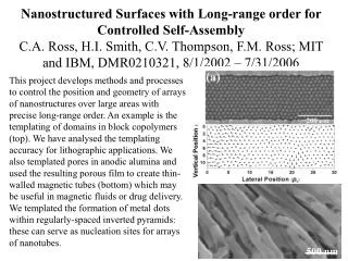
This research focuses on forming InGaAs FinFETs with sub-10nm width and 200nm height using Atomic Layer Epitaxy for improved electrostatics and drive current. The process flow involves channel growth, gate dielectric, metal deposition, and regrowth for enhanced integration density.

E N D
IEEE Device Research Conference, June 24-27 2013, Notre Dame Formation of Sub-10 nm width InGaAs finFETs of 200 nm Height by Atomic Layer Epitaxy *D. Cohen-Elias1, J.J.M. Law1, H.W. Chiang1, A. Sivananthan1, C. Zhang1, B. J. Thibeault1, W.J. Mitchell1, S. Lee1, A.D. Carter1, C.-Y. Huang1, V. Chobpattana2, S. Stemmer2, S. Keller1, M. J.W. Rodwell1 1ECE and 2Materials DepartmentsUniversity of California, Santa Barbara, CA
Goal: FinFET with 2-4 nm Body Thickness Intel Lg=60nm III-V FinFET (IEDM 2011) 30 nm fin: too thick at 60 nm gate length For good electrostatics, need fin thickness ~ (gate length/2) S. H. Park et al., NNIN Symposium Feb 2012. 8nm gate length → need <4 nm thick fin
Goal: Tall Fins for High Drive Current Goal: large on-current from small transistor footprint. Transistor Width Jsurf Jsurf Height Jsurf D Jsurf S Pitch Goal: fin height >> fin pitch (spacing)
Goal: Fins with Integrated N+ Source/Drain regrowth→ small S/D pitch → High Integration Density
Why Not Dry-Etch a 2nm Fin ? Goal: 2-4 nm thickness, 100+ nm height *metallization-induced damage increases Dit:Burek et al, JVST B. 29,4, Jul/Aug 2011; Dry-etching may well do similar surface damage serious process challenges
FinFETs by Atomic Layer Epitaxy Fin thickness defined by Atomic layer epitaxy (ALE) HfO2 → nm thickness control Fin~8nm TiN Fin height defined by sidewall growth → 200 nm high fins thin, tall fins → few-nm Lg , high currents
ALE-Defined finFET: Process Flow Dummy Gate Fin Template Channel ALE Gate Dielectric Gate Metal S/D Metal S/D Regrowth Release Fins
Fin Template (011) SiN hard mask: Ridges oriented along [011] H3PO4 : HCL etch: facet-selective, material-selective forms vertical (011) sidewalls stops on InGaAs etch-stop InGaAs etch-stop: defines template height→ defines fin height
Channel Growth by Atomic Layer Epitaxy 1 monolayer growth per cycle. InGaAs monolayer ~ 2.9A → S.P. DenBaars, P.D. Dapkus Journal of Crystal Growth, 98 (1989) TBA flow H2 flow TMI+ TMGa flow H2 flow → → → Using UCSB MOCVD : 1.7 Monolayer of InGaAs / Cycle (Not true ALE mode)
Channel Growth by Atomic Layer Epitaxy Growth: lattice-matched InGaAs 20 ALE cycles → <10 nm channel Masked growth: no InGaAs growth on top of template Details: one ALE cycle = 10 sec TMGa/TMI, 10 sec H2 , 10 sec TBAs, 10 sec H2 450 C growth
Dummy Gate: Patterns Source and Drain HSQ Mask HSQ* : E-beam definable SiO2 ALD Al2O3 mask sub-layer: adhesion *HSQ: Hydrogen silsesquioxane
Source Drain Regrowth Drain HSQ Source MOCVD Regrowth 600C lattice-matched N+ InGaAs, 5*1019/cm3 doping
S/D Regrowth: Filling vs. Sidewall Regrowth Present process: S/D regrowth partly fills spaces between fins Target process: S/D sidewall regrowth by ALE → large contact area → low access resistance
Source Drain Regrowth Drain HSQ Source
Fin Release fin release: H3PO4:HCl selective wet-etch etches InP stops on InGaAs
Fin Release N+ fin without N+ regrowth fin with N+ regrowth N+
Why Not Release Fins Before S/D Regrowth ? Images of released ~10 nm fins: S/D regrowth provides mechanical support
ALD Gate Dielectric, ALD Gate Metal HfO2 and TiN ALD gate Stack Source Drain
Source and Drain Metal Gate Source Metal Drain Metal
TEM Images HfO2 Fin~8nm TiN
Where is the DC Data ? Planar InAs/InGaAs MOSFET Present finFETs: very high leakage Planar FET: thermal Ni gatefinFET: ALD TiN gate interface damage ? Planar FET: 100 interfacefinFET: 011 interfaces ALD surface preparation ? Lee et al, 2013 VLSI symposium
3-D Transistors to Extend Moore's Law Lundstrom: high S/D tunneling @ 4-7 nm Lg → increase m* as Lg decreases Implication: FETs won’t improve with scaling increased m* → decreased vinj → decreased Ion , increased CV/I If we scale only to increase the IC packing density, why reduce Lg ? Alternative: 3-D integration ...or other geometries... height>> pitch
FinFETs by Atomic Layer Epitaxy ALE-defined fin → few-nm thick channels → scaling to 8nm gate length HfO2 Fin~8nm 200 nm fin height →enhance drive current TiN Jsurf Jsurf Jsurf D Jsurf S


![Nm]](https://cdn3.slideserve.com/6300766/slide1-dt.jpg)