Principles of Optical Microscopy and Imaging Techniques
Learn about the principles of optical microscopy, including illumination and imaging conjugate planes. Explore various microscopy techniques such as brightfield, phase contrast, and fluorescence microscopy.

Principles of Optical Microscopy and Imaging Techniques
E N D
Presentation Transcript
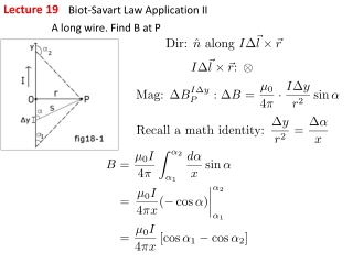
Lecture 19 Principles of optical microscopy
Illumination conjugate planes are shown in red; an image of the lamp filament is in focus at these planes Imaging path conjugate planes are shown in red; an image of the specimen is in focus at these planes http://www.microscopyu.com/articles/formulas/formulasconjugate.html
Transillumination Field diaphragm: will affect size of field that is illuminated at the focal plane Condenser aperture: will affect the numerical aperture of the condenser http://www.microscopyu.com/tutorials/java/conjugateplanes/index.html
Epi-illumination Field diaphragm: will affect size of field that is illuminated at the focal plane Aperture diaphragm: will affect the numerical aperture of the objective for illumination
Brightfield or trans-illumination microscopy • Simplest type of microscopy • Contrast provided by absorption • Biological specimens are not highly absorbing naturally • Use stains, which typically require fixation, i.e. cells no longer alive • Used routinely in histopathology and hematology and basic science studies for which looking at live specimen is not crucial Tissue histology Blood cells
Phase contrast microscopy • First microscopic method which allowed visualization of live cells in action • Nobel prize in physics was awarded to Frits Zernike in 1953 for its discovery • It enhances contrast in transparent and colorless objects by influencing the optical path of light • It uses the fact that light passing through the specimen travels slower than the undisturbed light beam, i.e. its phase is shifted
Phase contrast microscopy • Let S (red) be light passing through medium surrounding sample and D (blue) light interacting with specimen. S and D typically interfere to yield P (green), which is what we can usually detect. • P will be phase shifted compared to S, but our eyes cannot detect phase shifts. • Phase contrast microscopy effectively converts this phase shift into an intensity difference we can detect
Phase contrast microscopy • Condenser annulus allows only ring of light to reach the condenser. • Light rays illuminating the sample but not interacting with it will go straight through and be imaged along a ring at the back focal plane of the objective • Light rays diffracted by the sample are phase shifted by a approximately a quarter wavelength and will be scattered over a range of angles and will generally not propagate in the exact forward direction • A phase plate at the back focal plane of the objective alters selectively the phase and magnitude of the non-diffracted wave. Phase plate http://www.microscopyu.com/tutorials/java/phasecontrast/positivenegative/index.html (ex) http://www.microscopyu.com/articles/phasecontrast/phasemicroscopy.htm (reference)l
Differential interference contrast • Differential Interference Contrast (DIC) microscopy converts phase shift gradients across different parts of a specimen into intensity differences. • Doesn’t suffer from some artifacts seen in phase contrast • Uses full NA of objective http://www.olympusmicro.com/primer/techniques/dic/dicintro.html
DIC image of nematode embryo • Mouse fibroblast embryo, 24.3 hour time lapse video http://www.microscopyu.com/moviegallery/livecellimaging/3t3/index.html
Principle of fluorescence Principle of Fluorescence1. Energy is absorbed by the atom which becomes excited.2. The electron jumps to a higher energy level.3. Soon, the electron drops back to the ground state, emitting a photon (or a packet of light) - the atom is fluorescing.
Fluorescence Stoke’s shift • Fluorescence emission peak wavelength is red-shifted with respect to absorption peak wavelength • This shift may vary typically from 5 to more than 100 nm, depending on the electronic structure of the molecule
Advantages of fluorescence • Highly sensitive method • Simple implementation • Highly sophisticated fluorescent probes • Fluorescent dyes that accumulate in different cellular compartments or are sensitive to pH, ion gradients • Fluorescently tagged antibodies to specific cell features • Endogenously expressed fluorescent proteins • Really endogenous NADH/FAD: enzymes involved in ATP production structural proteins: collagen/elastin amino-acids: tryptophan/tyrosine • After gene modification Green fluorescent protein and variants
Optical path of fluorescence microscope Dichroic filter: reflects excitation and transmits fluorescence http://www.microscopyu.com/articles/fluorescence/fluorescenceintro.html
You can image simultaneously or sequentially the same sample at different excitation emission wavelengths to look at different cell components • Cell nucleus stained with blue Hoechst dye • Mitochondria stained with Mitotracker red • Actin cytoskeleton stained with phalloidin derivative conjugated to Alexa 488 (green)
Photobleaching often limits the number of exposures or the exposure time Photobleaching is the irreversible photochemical destruction of the fluorescent chromophores
Resolution is limited in thick specimens by detection of out-of-focus fluorescence • In a standard fluorescence microscope, the excitation beam illuminates uniformly a wide field of the sample. • If the sample is thick, fluorescence will be excited within the focal plane, but also within planes above and below the focus. • Some of this fluorescence will be imaged onto the detector and will result in a defocused-looking image Human medulla rabbit muscle pollen grain fibers
Principle of confocal microscopy In confocal microscopy two pinholes are typically used: • A pinhole is placed in front of the illumination source to allow transmission only through a small area • This illumination pinhole is imaged onto the focal plane of the specimen, i.e. only a point of the specimen is illuminated at one time • Fluorescence excited in this manner at the focal plane is imaged onto a confocal pinhole placed right in front of the detector • Only fluorescence excited within the focal plane of the specimen will go through the detector pinhole • Need to scan point onto the sample
To create confocal image, scanning is required • Either specimen is scanned past excitation beam or laser beam is scanned across specimen • For biological experiments, it is most common to scan the laser beam across focal plane using a combination of two galvanometric-driven mirrors
Optical train of a confocal microscope CONFOCAL SCANNING LASER MICROSCOPE
Optical train of a confocal microscope CONFOCAL SCANNING LASER MICROSCOPE
Elimination of out-of focus fluorescence yields superior images http://www.olympusfluoview.com/theory/confocalintro.html
A thick specimen can be optically scanned in three dimensions and the images can be processed to yield cross-sections along plane of interest, three dimensional composites and animations Hamster ovary cells Mouse intestine Pollen grain http://www.olympusfluoview.com/java/scanningmodes/index.html
In vivo depth-resolved imaging is possible Tumor cells grown subcutaneously in mice, expressing Green Fluorescent Protein Blood vessels stained with Cy5-conjugated anti-PECAM antibody Study interactions of tumor cells with their environment and potential factors/drugs that affect processes, such as tumor growth or metastasis
Video rate microscopy captures dynamic interactions • Monitor cell-cell, cell-environment interactions in natural environment to understand animal and human biology and processes involved in disease development • Monitor dynamic interactions
ROTATABLE HEAD MECHANICAL ARM 3-AXIS TRANSLATION STAGE OBJECTIVE LENS HOUSING RING-AND-TEMPLATE (attached to skin and locks into the housing) In Vivo Reflectance Confocal Microscopy of human skin VivaScope by Lucid Courtesy of S. Gonzalez
OPTIMUM RANGE PARAMETERS FOR RCM OF HUMAN SKIN • Wavelengths 400-700 nm (visible) 800-1064 nm (NIR) • Refraction index medium 1.33 (water) • Objective lenses 30 -100X, 0.7-1.2 NA • Detector aperture diameter 100-200 µm • Imaging Rate 10-30 frames/sc • Illumination Power up to 40 mW • Tissue Stability M-T clamping fixture
H&E Confocal in vivo SC SG SS DEJ 180 µm 100x, 1.2NA Reflectance-mode Confocal Microscopy Live Normal Skin “En face” SECTION VERTICAL Hematoxylin & Eosin stained section of tissue Rajadhyaksha M, González S, et al. J Invest Dermatol 1999;113;293-303.
Courtesy of S. Gonzalez 60 x, 0.85 NA x y 20 µm Elongated nuclei - Monomorphism Uniform Polarization of nuclei Stained in vitro section In vivo confocal 250 µm
Courtesy of S. Gonzalez OVERALL SENSITIVITY AND SPECIFICITY Criteria Sensitivity % Specificity % Elongated monomorphic nuclei 100 71 Polarized nuclei 92 97 Inflammatory infiltrate 83 55 Increased vascularity 88 54 Pleomorphism 64 64 2 or more criteria 100 54 3 or more criteria 94 78 4 or more criteria 83 96 Results remained reliable across study sites and across Basal Cell Carcinoma subtypes. Combination of clinical photograph examination and reflectance confocal microscopy evaluation significantly improved non-invasive diagnosis of BCC
Multiphoton microscopy • At very high photon densities, it becomes possible for two or more photons to be simultaneously absorbed • Each multiple absorption induces a molecular excitation of a magnitude equivalent to the sum of the absorbed photon energies http://www.aep.cornell.edu/drbio/MPE/mpe.html
Multi-photon fluorescence: Basic principles • Multi-photon excitation is a nonlinear process • Because two photons are required for each excitation, the rate of two-photon absorption depends on the square of the instantaneous intensity. • Because of the large intensities required, high power lasers providing very short pulses (~100 fs) are used, so that peak intensity is high, but average power doesn’t damage the specimen. • We have photon flux densities sufficiently high for multiple photons to arrive “simultaneously” (in 10-15 s) at an excitable molecule (of 10-16 cm2 cross section) only at the focus point of a beam. • The probability that a given fluorophore at the center of a focused beam absorbs a photon pair during a single pulse is
Advantages of multi-photon excitation • With a single-photon source excitation occurs throughout the beam profile • With a two-photon source excitation events are limited to the beam focus • Focal point restriction of excitation automatically provides 3-dimensionally resolved submicron information • Photodamage is restricted to the focal plane • Not necessarily to refocus the fluorescence through an aperture • Simpler, more efficient optical detection design • Scattering in thick specimens degrades signal to a smaller extent • UV absorbing molecules can be excited using practical visible/NIR wavelength ranges
Second Harmonic Generation (SHG) http://www.aep.cornell.edu/eng10_offsite.cfm?URL=http%3A%2F%2Fwww%2Edrbio%2Ecornell%2Eedu • SHG can be thought off as the scattering equivalent of two-photon excited fluorescence • The emitted photons are at exactly half of the wavelength of the incident radiation (as excitation l changes, emitted SHG signal l also changes) • The SHG signal is phase matched to the incident radiation and it is emitted in a highly directional fashion, which depends on the size, shape and refractive index of the scatterers. (fluorescence is incoherent and isotropic)
Instrumentation http://www.aep.cornell.edu/eng10_offsite.cfm?URL=http%3A%2F%2Fwww%2Edrbio%2Ecornell%2Eedu
Multi-photon imaging is the method of choice for looking at endogenous fluorescence in thick biological specimens Two-photon excited fluorescence (TPEF) is particularly useful in imaging of endogenous weak fluorescence Second harmonic generation (SHG) yields excellent intrinsic contrast for imaging of asymmetric molecules, such as collagen http://www.drbio.cornell.edu/Infrastructure/MPM_WWW/MPM_hist/home.htm
4-Pi, two-photon fluorescence microscopy • Combines localized excitation with coherent fluorescence detection to beat resolution limit • Resolution achieved 80 nm Mitochondrial network of a live yeast cell Gugel et al. Biophys J 2004; 87:4146-4152