Download
1 / 30
300 likes | 471 Vues
Aditya Kawatra 2004EE10313. Rake Reception in UWB Systems. UWB and Rake Reception. Impulse radio UWB is being considered for a variety of applications including as a possible physical layer for emerging wireless personal area networks (WPANs).

E N D
Aditya Kawatra 2004EE10313 Rake Reception in UWB Systems
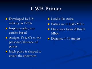
UWB and Rake Reception Impulse radio UWB is being considered for a variety of applications including as a possible physical layer for emerging wireless personal area networks (WPANs). UWB systems have BW utilization > 500 MHz or fractional BW > 25% Sub-nanosecond pulses, high data rates possible Channel usually consists of many multi-path reflections – empirically confirmed
UWB and Rake Reception To this effect, many multi-path modeling channel models have been proposed, e.g. Saleh-Valenzuela double exponential ray-cluster model; tapped delay line model; IEEE CM1, CM2 etc UWB exhibits high resolution among the multi-path arrivals due to the extremely short duration of the pulses To exploit this multipath diversity, rake receivers are used (to inc. diversity order)
Rake Receiver Principles Basic version consists of multiple correlators (fingers) where each of the fingers can detect/extract the signal from one of the multipath components provided by the channel. The outputs of the fingers are appropriately weighted which can be determined by a few procedures A few of them are MRC (Maximal Ratio Combining), MMSE (Minimal Mean Squared Error), OC (Optimal Combining) etc.
Rake Receiver Principles Rake filters are mainly categorized on the number of rakes like A-Rake (All Rake), P-Rake (Partial Rake) and S-Rake (Selective Rake) Diff b/w S-Rake and P-Rake S-Rake is sort of best fit and P-Rake is sort of first fit. Tradeoff between BER (SER) and Time Complexity (hence data rate) at the receiver.
MRC Rake In MRC, as name suggests, the rakes are chosen in which the signal-to-noise ratio is maximized. In a typical MRC S-Rake with ‘N’ fingers, the received signal is passed through a pulse-shaping filter. This is sampled at symbol, chip or sub-chip rate The delays, amplitudes and phases of (>N) multipaths are estimated
MRC Rake • Then, the fingers having the largest ‘N’ amplitudes are chosen • The signals of the selected fingers are then despreaded by correlators • Then they are weighed by their respective estimated amplitudes and coherently added • Then a decision maker makes the bit decision
Issues with MRC Rake • If the signals in the rakes are uncorrelated and have same noise power then maximum theoretical performance is achieved • But the signals are usually correlated, decreasing performance • If the sampling rate is sub-chip rate then synchronization errors are removed. • However this means higher sampling rates and thus higher time complexity
Issues with MRC Rake • Chip and symbol rate based receivers have much lower complexity • However, finding the optimum sampling point is a problem -> timing error (jitter)
MMSE Rake • In MMSE, attention is paid to the rake weights • Particular case of OC Rake • Basically, the weight vector is improved after each iteration • The mean square error between the expected decision value (for each bit) and the measured decision value is minimized. • The correlator is assumed to have perfect knowledge of the channel delays and amplitudes (by way of training)
MMSE Rake mathematically In most general form, Here, p(t) ≡ basic pulse shape, Tf ≡ Average Pulse Time Cj = Time-hopping code, Tc = Chip time and NcxTc <= Tf Energy in q(t) is taken to be 1. Assuming biphase modulation received signal is, rk(t) = dk*sqrt(Eb)*q(t-k*Ts)*h(t) + n(t)Here, dk is data bit from {1,-1}, Eb is bit energy at receiver, Ts is symbol time (bit time), h(t) is channel response and n(t) is received noise
MMSE Rake mathematically Let v(t) = template at correlator = q(t) [biphase mod.] Corresponding to the lth finger and tl delay of template, Output at correlator = This is = dk*sqrt(Eb)*hl + nl,k In vector form, xk = dk*sqrt(Eb)*h + nk Dk’ = (Transpose(w)*xk), the measured decision value
MMSE Rake mathematically The Mean Square Error is given by : MSE = E(||dk – Transpose(w)*xk||)2 The optimal vector satisfying MMSE is givn by wo = argminw(MSE) The Weiner solution is given by, wo = A*M-1*h, A being a scaling constant M is the correlation matrix of noise = E[Transpose(nk)*nk] And E is Expectation of (Mean)
MMSE Rake mathematically • Instead of calculating wo iteratively by this method, the LMS (Least Mean Square) Algorithm is Utilized • In this after every iteration, w(n+1) = w(n) + mu*Err*xk where mu = small positive const. Err = Error = (dk – dk’) xk= Correlation vector
MMSE Rake mathematically • The convergence and stability of this algorithm depends on mu. The lower it is, the slower it converges but the stability is assured • Also, the algorithm is known to be of lower time complexity than the previous solution
Simulation Log • Gaussian double derivative (with energy = 1) was taken as the basic pulse shape • Channel model was the Saleh-Valenzuela channel model with minimum inter-ray spacing equal to the symbol time to demonstrate multipath resolution of UWB reception • Then a pulse train was convoluted with the channel impulse response and ouput confirmed to be multipath resolvable
Simulation Log • Then MMSE Partial-rake was performed (by taking arbitrary fingers) • Using the LMS algorithm, the decision was taken on the correlator outputs • The input size was taken to be 1000 (due to time constraint) and BER’s analyzed • As the signal strength was increased, the BER ‘overall’ decreased • Also, on increasing the number of fingers the BER decreased somewhat
Simulation Log • Then, Selective Rake was taken and simulated the same way • It was found to give slightly lesser BER for the same SNR compared to partial rake • Also, as the number of rakes increased the BER correspondingly decreased
Coding Gain • Selective Rake has coding gain of 1.25 dB over Partial Rake for a BER of 15/1000 in our modified example • Higher no. of bits could not be taken because of the amt. of computing time