Download
1 / 35
350 likes | 377 Vues
Investigating beam propagation, optics damage, and laser influences in Fusion Energy Systems. Addressing challenges to optimize laser components and enhance system performance. Conducting cutting-edge research to achieve superior laser functionality and lifetime. Research initiatives aim to understand material properties and environmental factors affecting laser performance, with a focus on optimization strategies for advanced Fusion Energy Systems.

E N D
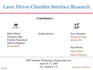
Laser Driver-Chamber Interface Research Contributors: Stephen Payne Nasr Ghoniem Zhiqiang Wang* Qiyang Hu* Neil Morley Sandy Quan* James Williams* Mark Tillack Tak Kuen Mau Farrokh Najmabadi Mofreh Zaghloul Dustin Blair* IFE Chamber Technology Program Review April 26-27, 2001 Los Angeles, CA *graduate students (4/25/01)
Title of Work: Laser Driver-Chamber Interface Studies Principal Investigators:M. Tillack (UCSD), S. Payne (LLNL), N. Ghoniem (UCLA) Overall Objective:Demonstrate acceptable performance and lifetime of transmissive and reflective final optics and the ability to deliver driver energy on target within specifications. Technical Approach:(1) Establish damage criteria through detailed analysis; (2a)Develop mesoscopic models of surface deformationof metalsand solve continuum equations for generation/diffusion/interaction/deformation; (2b) Fabricate, characterize and test metal mirrors; (3) Perform irradiation tests on Si2O and CaF2; (4) Study beam propagation physics experimentally and analytically. Accomplishments: • Established GIMM damage criteria through analysis of wave propagation • Developed new algorithms and analyzed surface deformation instability • (Built new laboratory and)Operated an Al GIMM beyond the normal-incidence LIDT • Determined transmissive optic darkening (g and n+ g) andeffectiveness of annealing • Analyzed and tested liquid fracture from a GILMM Relevance to OFES/Fusion: “Final optics” is one of the top 4 IFE power plant issues described in the FESAC-IFE review panel (1996), see Table 1: http://aries.ucsd.edu/PUBLIC/INFO/FESAC_IFE96.html Funding (past 3 years): FY00 $510KFY01 $370K
This program emphasizesscientific explorationapplied to solving the key issues for IFE Primary research objectives: 1. Understand the effects of surface defects on beam propagation and establish criteria for surface degradation. 2. Understand the mechanisms oflaser damage in metals and find material and mechanical design solutionsto maximize theLIDT and lifetime of GIMM’sin the fusion environment. 3. Understand the formation of color centers in transmissive optic materials and demonstrate an acceptable solution to reduce the effects (e.g., by annealing). 4. Understand the physics of gas ionization by lasers at low pressure and environmental effects on beam propagation. Establish criteria on chamber media.
Outline • Background • Design options, research goals, issues and requirements • Grazing incidence metal mirror research • Laser-induced damage modeling • Damage experiments • Modeling of beam degradation • Neutron damage to transmissive optics • Laser propagation in IFE chambers
Geometry of the Driver-Chamber Interface (20 m) Grazing incidence mirrors (30 m) (SOMBRERO values in red) Prometheus-L reactor building layout Si2O or CaF2 wedges
Final Optic Damage Threats Final Optic Threat Nominal Goal Optical damage by laser >5 J/cm2 threshold (normal to beam) Sputtering by ions Wavefront distortion of <l/3 * (~100 nm) Ablation by x-rays (6x10⁸ pulses in 2 FPY: (~25 mJ/cm2, partly stopped by gas) 2.5x10⁶ pulses/allowed atom layer removed) Defects and swelling induced by Absorption loss of <1% g-rays (~3) and neutrons (~18 krad/s) Wavefront distortion of < l/3 * Contamination from condensable Absorption loss of <1% materials (aerosol and dust) >5 J/cm2 threshold Two main concerns: • Damage that increases absorption (<1%) • Damage that modifies the wavefront – • spot size/position (200mm/20mm) and spatial uniformity (1%) *“There is no standard theoretical approach for combining random wavefront distortions of individual optics. Each l/3 of wavefront distortion translates into roughly a doubling of the minimum spot size.” (Ref. Orth)
Outline • Background • Grazing incidence metal mirror research • Laser-induced damage modeling • Damage experiments • Modeling of beam degradation • Neutron damage to transmissive optics • Laser propagation in IFE chambers
Surface deformation leads to roughening and loss of laser beam quality • Single Shot Effects on LIDT: • Laser heating generates point defects • Coupling between diffusion and elastic fields lead to permanent deformation • Progressive Damage in Multiple Shots: • Thermoelastic stress cycles shear atomic planes relative to one another (slip by dislocations) • Extrusions & intrusions are formed when dislocations emerge to the surface, or by grain boundary sliding. • F1 varies from a few to ~ 10 J/cm2. • LIDT is a strong function of material & number of shots – it degrades up to a factor of 10 after only 10000 shots (survival to ~108 shots is needed). • Uncertainty in saturation behavior http://puma.seas.ucla.edu/web_pages
Surface deformation patterns after one laser shot of intensity near LIDT (Solution of continuum equations with defect diffusion in the self-consistent elastic field) Focused Laser-induced Surface Deformation (vacancy density correlates with deformation) Uniform Laser-induced Surface Deformation Computer Simulation Computer Simulation Experiment (The model correctly predicts number of arms) (Walgraef, Ghoniem & Lauzeral, Phys. Rev. B, 56, 23, (1997) 1536) Focused laser-induced surface deformation (Lauzeral, Walgraef & Ghoniem,Phys. Rev. Lett. 79, 14 (1997) 2706)
Progressive damage in multiple shots is caused by successive dislocation slip & grain boundary sliding Low Density High Density
Outline • Background • Grazing incidence metal mirror research • Laser-induced damage modeling • Damage experiments • Modeling of beam degradation • Neutron damage to transmissive optics • Laser propagation in IFE chambers
GIMM development issues* Experimental verification of laser damage thresholds Protection against debris and x-rays (shutters, gas jets, etc.) Wavefront issues: beam smoothness, uniformity, shaping, f/number constraints Experiments with irradiated mirrors In-situ cleaning techniques Large-scale manufacturing Cooling * from Bieri and Guinan, Fusion Tech. 19 (May 1991) 673.
Aluminum is the 1st choice for the GIMM Normal incidence reflectivity of metals • Lifetime of multi-layer dielectric mirrors is questionable due to rapid degradation by neutrons• Al maintains good reflectivity into the UV• Al is a commonly used mirror material – easy to machine, easy to deposit• Thin (~10 nm), protective, transparent oxide • Normal incidence damage threshold ~0.2 J/cm2• Grazing incidence raises s-reflectivity to >99%• Larger footprint reduces fluence by cos(q)• Combined effects hopefully raise the damage threshold to >5 J/cm2
Engineered surfaces: we have fabricated and characterized several kinds of Al surfaces 75 nm Al on superpolished flat: ±2Å roughness, 10Å flatness diamond-turned Al 6061 Al 1100 showing grain boundaries and tool marks MgSi occlusions
The UCSD laser-plasma and laser-material interactions lab is used for damage tests (Good beam diagnosis is essential to understanding damage effects) Spectra Physics YAG laser: 2J, 10 ns @1064 nm; 800, 500, 300 mJ @532, 355, 266 nm Peak power density ~1014 W/cm2 100 ppm accuracy Reflectometry Class 100cleanroomenclosure Profiling Shack-Hartmann
Damage depends strongly on the surfacemorphology and angle of incidence Surface defects in Al 6061 preferentially absorb light, causing explosive ejection of occlusions 4000x Several shots at 80˚, 1 J/cm2 Several shots at normal incidence, 0.2 J/cm2 Measurements are ongoing: purer surfaces, steeper angles, longer exposures, recrystallization of amorphous coatings http://aries.ucsd.edu/Etech/ife.shtml
Analysis and initial experiments for GILMM indicate possibility of high “damage” threshold for this alternative idea Hg surface 57 ms after the laser pulse. No motion detectable Hg surface 1 ms after the laser pulse. Wave amplitude estimate 0.81 mm ABLATOR code results: • No surface spallation damage limit predicted for slow compression beams (20 ns). Damage limit for fast ignitor beams (10 ps) in the 1-10 J/cm2 range High energy density experiments: • Large surface waves from 3 ns, 1 J/cm2 absorbed, 1mm wavelength laser impulse die out in 50 ms Beam-normal “damage limit” calculations for spallation for 10 ps, 1/3 m laser light
Outline • Background • Grazing incidence metal mirror research • Laser-induced damage modeling • Damage experiments • Modeling of beam degradation • Neutron damage to transmissive optics • Laser propagation in IFE chambers
Modeling the effects of damage on beam characteristics helps us establish damage limits
metal substrate n4, k4 coating n3, k3 n2, k2 contaminant n1, k1 q1 Incident medium Fresnel modeling quantifies the tolerable level of surface contamination - Reflectivity is reduced with increasing contaminant thickness. - Effect of surface contaminant is diminished at gracing incidence. - Carbon (k ~ n) degrades reflectivity much more than H2O (k ~ 0). 2 nm H2O film @80o 1 .8 .6 .4 .2 0 1 .8 .6 .4 80o 40o 80o 0o q1 = 0o H20 Carbon 80o Reflectivity Reflectivity 60o No film 2 nm C l = 248 nm 10 nm Al2O3 coating Al mirror 40o q1 = 0o 20o 80o q1 = 0o 0 1 2 3 4 0 20 40 60 80 Contaminant Thickness (nm) Al2O3 Coating Thickness (nm)
Specularly reflected intensity is degradedby induced mirror surface roughness Isc q2 q1 The effect of induced surface roughness on beam quality was investigated by Kirchhoff wave scattering theory. For cumulative laser-induced and thermomechanical damages, we assume Gaussian surface height statistics with rms height s. 1.0 0.8 0.6 0.4 0.2 0 Iinc q1 = 80o Intensity Degradation, e–g 70o 60o Io : reflected intensity from smooth surface Id : scattered incoherent intensity g : (4ps cosq1/l)2 e.g., at q1 = 80o, s/l = 0.1, e-g = 0.97 0 0.1 0.2 0.3 0.4 0.5 s / l • Grazing incidence is less affected by surface roughness • To avoid loss of laser beam intensity, s / l < 0.01
Outline • Background • Grazing incidence metal mirror research • Laser-induced damage modeling • Damage experiments • Modeling surface damage effects on beam quality • Neutron damage to transmissive optics • Laser propagation in IFE chambers
Neutrons and g-rays create defects in SiO2 which result in photon absorption Oxygen Deficient Center (ODC, 246 nm) n0 Normal Site neutrons Si Si O Si Si O2- Full thermal recovery g-rays Non-Bridging Oxygen Hole Center (NBOHC, 620 nm) Si+ Si Si O- Si T < 200 C E’ Center (213 nm) T > 400 C Si O Si Strained Si -O Bonds (350-750 nm)
We have discovered that IFE-relevant MeV g / n° irradiation doses of fused silica lead to significant absorption at 350 nm Dose = 100 GRad of n° = IFE-Relevant exposure of ~2 months at LANSCE Absorption Coefficient (cm-1) T=426˚C T=105˚C Residual defects remaining in Si2O depend on temperature 620 nm band is due to the “non-bridging oxygen hole center,” while the slow rise may be due to “strained Si-O bonds” Under these conditions, final optics last ~1 month May be possible to reduce absorption further by annealing at higher temperatures (e.g., ~ 700 °C for 24 hrs)
MeV g / n° irradiation of CaF2 at room temperature also leads to the formation of color centers 1 Mrad g-rays (60Co), post-annealing 766 kRad n˚ Absorption Coefficient (cm-1) Annealed at 385˚C (Goal ~0.01/cm) • 10 MRad g-irradiation (60Co) yields no color centers for virgin sample • Absorptions at 335, 410, and 540 nm due to color centers • Color center is a “missing fluorine” that captures an electron • Annealing removes absorption due to n0 induced color centers • CaF2 is “softened” by n0 (g-irradiation induces color center of annealed sample)
Outline • Background • Grazing incidence metal mirror research • Laser-induced damage modeling • Damage experiments • Modeling surface damage effects on beam quality • Neutron damage to transmissive optics • Laser propagation in IFE chambers
Laser propagation near or beyond the breakdown threshold is uncertain • Laser intensity near the target: 1013 – 1014 W/cm2 • Threshold intensity is not well-defined; laser light partially ionizes chamber gas at any intensity • Gas “breakdown” occurs when plasma density is high enough that a substantial amount of laser light is absorbed (avalanche process). Data for Xe, except Turcu • Previous work: breakdown threshold defined as intensity at which visible light is emitted from the focal spot (most of the visible light is generated by the interaction of electrons generated by ionization of the background gas with the neutral gas atoms). • Wavefront distortion can occur at lower (or higher) plasma densities and laser intensities, changing the beam profile on the target. This “threshold” intensity will depend on the required degree of beam smoothness on the target, f number of the lens, beam coherence, etc. • Multi-species and contaminated environmental conditions further complicate the physics.
Experimental setup for laser propagation tests Initial measurements: • Visible light emission from the focal spot • Variation in laser energy intensity and temporal pulse shape • Wavefront variation Planned: • Emission spectroscopy 25 cm Design allows for interchangeable optical boards to be inserted through the side of chamber. Final design of the vacuum chamber is completed and parts ordered. Emphasis of OFES program beginning to shift into chamber physics.
Outline • Background • Grazing incidence metal mirror research • Laser-induced damage modeling • Damage experiments • Modeling surface damage effects on beam quality • Neutron damage to transmissive optics • Laser propagation in IFE chambers • Applications
The science and technology of optics and laser-material interactions have widespread applicability to industry • Robust high-power optics are needed in many terrestrial, airborne and space-based applications • Laser-material interactions research is helping to improve laser micromachining techniques* Governing physics is very similar to IFE • Laser absorption in surface • Thermal response of surface • Liquid hydrodynamics • Evaporation • Unsteady gas dynamics (including chamber environment) • Condensation • Laser-cluster interaction * work partially supported by Hewlett Packard
Closing Remarks This relatively young program is already producing valuable results. We are prepared to accelerate progress on the key laser driver-chamber interface issues, thanks to growing synergisms with related OFES and DP programs. The field of laser interactions offers exciting opportunities to contribute across a broad range of leading-edge sciences and technologies.
Summary of laser driver/chamber interface work Quality of science and technology: Scientific methods and approaches Modeling: • Meso-scale modeling of mechanical response to repeated laser irradiation • Modeling of the generation of sub-surface defects and their effects on surface deformation and roughening • “Kinetic modeling” of defect annealing • Optical modeling: Fresnel, Kirchhoff scattering theory, ZEMAX Experiments: • Irradiation tests of fused silica and CaF2 • GIMM surface damage tests • Wavefront measurements • Determination of optic darkening and effectiveness of annealing • Fabrication and characterization of several mirror types, initial damage tests
Summary of laser driver/chamber interface work Productivity and progress: • Coordinated as a national team: LLNL, UCLA, UCSD (with support from GA, LANL, SNLA) • Experimental progress • Creation of the UCSD laser lab, fabrication and characterization of mirrors, initial damage test results • Determination of optic darkening and effectiveness of annealing • Modeling progress • Determination of contamination and defect limits by wavefront modeling • Meso-scale modeling of thermo-mechanical response to repeated laser irradiation • Modeling the generation of sub-surface defects and their effects on surface deformation and roughening • Rate of progress: this program is <2 yrs old. Some parts initiated within past year
Summary of laser driver/chamber interface work Relevance and impact: • Driver-chamber interface is one of the top 4 issues for IFE • Contributions to optical engineering, materials science, laser-ablation fields • Publications in both fusion and non-fusion literature • 5 graduate students supported by this activity • Technology transfer to laser optics and micromachining industries • Internationally unique program addressing laser driver-chamber issues in an integrated program
Selected Publications* *For complete list, see presentation by W. R. Meier Damage modeling • N. M. Ghoniem and M. S. Tillack, "Theory and Measurements of Laser-Induced Damage of Reflective Metal Mirrors in IFE Environments," 10th ICFRM (2001), to be published in J. Nucl. Mater. • D. Walgraef, N. M. Ghoniem and J. Lauzeral, "Deformation patterns in thin films under uniform laser irradiation," Phys. Rev. B 56 (23) December 1997. Damage experiments • M. S. Tillack, S. A. Payne and N. M. Ghoniem, "Damage threats and response of final optics for laser-fusion power plants," 2nd Int. Symp. on Inertial Fusion Science and Applications, Kyoto Japan, Sept. 2001. • M. Zaghloul and M. S. Tillack, “Laser-induced damage to metal mirrors for laser-IFE final optics”, 19th IEEE/NPSS Symposium on Fusion Energy, Atlantic City, Oct. 2-5, 2001. Wavefront modeling • T.K. Mau and M.S. Tillack, "Modeling of Mirror Surface Damage Effects on Beam Propagation in a Laser-Driven IFE Power Plant", 19th IEEE/NPSS Symposium on Fusion Energy, Atlantic City, Oct. 2-5, 2001. Laser ablation • D. Blair and M. S. Tillack, "Particle Formation and Dynamics in the Laser Ablation Plume," submitted to the SPIE Conference on Micromachining and Microfabrication 21 - 25 October 2001, San Francisco, CA.