Project Diffusion
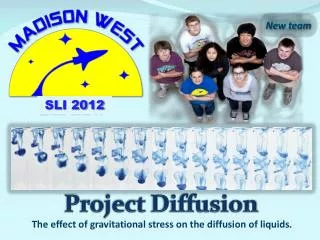
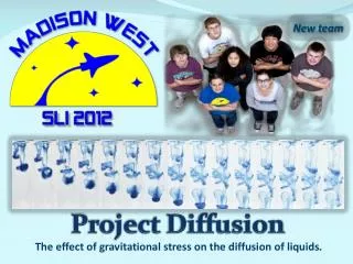
New team. Project Diffusion. The effect of gravitational stress on the diffusion of liquids . Part 1: Vehicle. Major Milestone Schedule. GANTT Chart. Mission Profile Chart. Event 3: Apogee at 16s, 4502ft. Coast. Drogue descent.

Project Diffusion
E N D
Presentation Transcript
New team ProjectDiffusion The effect of gravitational stress on the diffusion of liquids.
Mission Profile Chart Event 3: Apogee at 16s, 4502ft Coast Drogue descent Apogee prediction updated based on data from full scale full-impulse flight (Cd=0.65): 4502ft Event 2: Burnout at 2.24s, 1000ft Event 4: Main parachute deployment at 84s, 700ft Event 5: Landing at 110s, 0ft Event 1: Ignition at 0s, 0ft
Vehicle Success Criteria • Motor ignition • Stable flight • Altitude of 5,280 feet AGL reached but not exceeded(most current prediction: 4502ft) • Both drogue and main parachute deployed • Vehicle returns to the ground safely with minimal damage • Safe recovery of the booster
Vehicle Drawings CP 83.1” from nosecone CG 65.6” from nosecone Static margin 5.5 calibers Length 108” Diameter 5.5”(body tube), 4”(booster) Liftoff Weight 21 lbs with AT-K1050W Motor Aerotech K1050W
Construction Materials • Body:5.5”/4.0” LOC Precision fiber tubing • Fins: 1/32” G-10 fiberglass + 1/8” balsa sandwich, TTW mounted • Couplers: LOC Precision with stiffeners • Bulkheads, centering rings: 1/2” plywood • Motor mounts: 54mm Kraft phenolic tubing • Nosecone: Plastic nose cone • Rail buttons: standard nylon rail buttons • Motor retention system: Aeropack screw-on motor retainer • Anchors: 1/4" stainless steel U-Bolts • Epoxy: Locktite epoxy
Motor Selection • We selected the AT-K1050W 54mm motor to propel our rocket to reach, but not exceed an altitude of 5280ft AGL • The AT-K1050W motor provides an appropriate thrust to weight ratio for our vehicle (12.2). Mach delay of 4 seconds will be set on both deployment altimeters (the setting was successfully tested during full impulse test flight)
Altitude Profile Apogee 4502ft, 16s Cd = 0.65 (from flight data)
Acceleration Profile Max acceleration: 16g
Velocity Profile Maximum velocity 507 mph (Mach number: 0.66)
Ejection Charge Calculations Wp=dP*V/(R*T) • Wp - ejection charge weight [g] • dP - ejection pressure (15 [psi]) • V - free volume [in3] • R - universal gas constant (22.16 [ft-lb oR-1 lb-mol-1]) • T - combustion gas temperature (3,307 [oR])
Ejection Charges Charges have been finalized via static ejection tests. Per NASA recommendation we have upgraded our backup charges by 25% and delayed their activation. If primary charge fails, backup charge will “try harder”, otherwise it fires harmlessly in open air.
Verification Plan • Tested Components • C1: Body (including construction techniques) • C2: Altimeter • C3: Accelerometer • C4: Parachutes • C5: Fins • C6: Payload • C7: Ejection Charges • C8: Launch System • C9: Motor Mount • C10: Beacons • C11: Shock Cords and Anchors • C12: Rocket Stability
Verification Plan • Verification Tests • V1 Integrity Test: force applied; verifies durability. • V2 Parachute Drop Test: tests parachute functionality. • V3 Tension Test: force applied to shock cords; tests durability. • V4 Prototype Flight: tests feasibility of vehicle with scale model. • V5 Functionality Test: tests basic functionality of device on ground. • V6 Altimeter Ground Test: simulate altitude changes; verifies preset altitude events fire. • V7 Electronic Deployment Test: tests that electronics ignite deployment charges. • V8 Ejection Test: tests that deployment charges can deploy parachutes/separate components. • V9 Computer Simulation: RockSim predicts behavior of launch vehicle. • V10 Integration Test: payload fits smoothly and snuggly into vehicle, and withstands flight stresses.
Half Impulse Launch Objectives • Test drogue and main parachute deployment • Test flight electronics (altimeters and ejection charges) • Test separation of body tubes at ejection • Test validity of simulation results • Test rocket stability • Test durability of rocket
Half Impulse Launch Results Calculated Cd : 0.61 Apogee for full scale impulse vehicle (Cd=0.61): 4718 ft • Apogee- 3325ft • Rocksim prediction 3396ft • Time to apogee- 13.4s • Apogee events • Drogue deployment • Main event • Main parachute deploys at 700ft
Recorded Altitude Profile Apogee : 3325ft at 13.4s (drogue deployment) Drogue Descent: measured rate 43fps (average) Main parachute: deploys at 500ft Final Descent: measured rate 21fps(average)
Observed Problems Because of a construction error, our fin assembly separated from the rest of the rocket at apogee (due to deployment shock). The problem has been fixed by adding 12 screws. Our drogue parachute was by mistake tied far from its upper anchor point (this increases the chance of drogue not leaving the body). The problem has been solved by moving the drogue closer to its upper anchor point.
Full Impulse Launch Objectives • Test drogue and main parachute deployment • Test flight electronics (altimeters and ejection charges) • Test separation of body tubes at ejection • Verify the flight apogee will not exceed 1 mile • Verify fixes from half-impulse flight • Verify final predictions
Full Impulse Launch Results Calculated Cd : 0.65 Apogee for full scale vehicle (Cd=0.65): 4502 ft • Apogee- 4502ft • Rocksim prediction 4718ft • Time to apogee- 16s • Apogee events • Drogue deployment • Main event • Main parachute deploys at 700ft
Recorded Altitude Profile Apogee : 4502ft at 16.00s (drogue deployment) Drogue Descent: measured rate 54fps (average) Main parachute: deploys at 700ft Final Descent: measured rate 23fps (average)
Problems Observed Our rocket landed in the tree and we have lost some of its parts. This results in following issues: * MAWD altimeters are no longer available and we will be replacing them with StratoLogger altimeters. While we will have no opportunity to test the StratoLogger units ourselves before the launch in Huntsville, our sister team has used StratoLoggers with success during their full impulse test flight.
Delivery System Summary • Apparent coefficient of drag Cd=0.65 • Apogee prediction 4,500ft • Primary motor choice AT-K1050W • Work to be done • Improve surface finish (decrease Cd) • Remove surface protrusions (decrease Cd) • Search and pursue minor weight savings • Repair E-bay
Recovery System Summary To further reduce the drift, we’d rather use a smaller drogue than to decrease the size of the main parachute (the booster impact energy is near the allowed maximum of 75ft-lbf) • Work to be done • Replace lost parachute • Replace lost shockcord • Replaced possibly damaged altimeters • Repeat static ejection tests
Payload Summary We will investigate the effects of acceleration and vibrations during flight on the diffusion of dye into liquids using digital imaging.
Payload Objectives • Determine the effect of acceleration on the diffusion of dye into liquids • Determine the effect of vibrations on the diffusion of dye into liquids
Payload Success Criteria • Collected data from the camera and accelerometers is accurate • Vessels containing liquid do not leak • Dye is injected into the liquid correctly • Images from camera are received • Acceleration is recorded • Payload is recovered
Payload Assembly Battery Camera LED Syringe Servo
Payload Prototype Battery Camera LED Syringe Servo
Payload Electronics • Accelerometer / G-Switch module • LIS331 3D accelerometer • +/- 24g, 16 bit resolution • Digital interface • 1000Hz maximum sampling rate • GS21 G-switch (2.1g) • Powered by payload computer (3.3V) • Connected by a single ribbon cable • Payload Computer • Drives injector servos • Collects and stores acceleration data • Monitors accelerometer for liftoff detection • Monitors G-Switch for liftoff detection • Distributed regulated voltages • 3.3V for sensors • 5.0V for servos • Powered from a single pack of 6AA batteries • 80MHz, 32KB RAM, 8 core processor, 27 I/O pins • 128KB of EEPROM, 96KB available for data storage
Nikon AW100 Camera • Selection Rationale • Fits inside the payload chamber • Waterproof (in case of payload damage) • Minimum focus is 1cm (0.4”) • Full HD video 1920 x 1080 @ 30fps • Sufficient memory/battery capacity • Within the budget of our project ($300) • Robust design (designed for extreme sports)
Integration of Payload Modules Vertical module Horizontal module Horizontal module
Experiment Sequence Launch and Boost • Dye is injected into the solution • Camcorder records the diffusion process The experiment chamber is brightly lit using LEDs to prevent any exposure problems during recording
Experiment Sequence Coast and Apogee The camcorder continues to record the diffusion process until the vehicle reaches apogee. Accelerometer records acceleration data.