Download
1 / 19
190 likes | 329 Vues
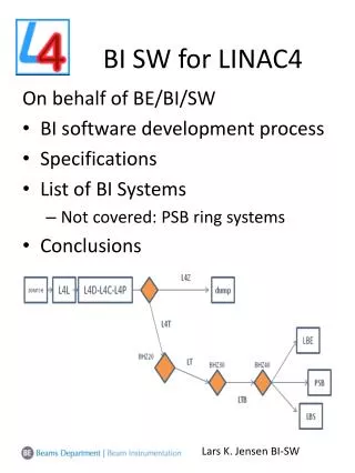
BI SW for LINAC4. On behalf of BE/BI/SW BI software development process Specifications List of BI Systems Not covered: PSB ring systems Conclusions. FESA framework. Application level. Daemons. OP GUIs. BI GUIs. CMW/Ethernet. VME front-end. Timing signals. Devices. Real-Time. COMM.

E N D
BI SW for LINAC4 On behalf of BE/BI/SW • BI software development process • Specifications • List of BI Systems • Not covered: PSB ring systems • Conclusions Lars K. Jensen BI-SW
FESA framework Application level Daemons OP GUIs BI GUIs CMW/Ethernet VME front-end Timing signals Devices Real-Time COMM SHM HW Lars K. Jensen BI-SW
Development • Hardware: • VME • PLC • Software: • Existing (L2, L3, PSB) • New ideas • BI Software • Low-level • Expert GUIs Specifications -COMM (OP/ABP/RF/BI ..) - OP-PSB Lars K. Jensen BI-SW
Hardware layout Host-name: cfv-xyz-bln4 (crate specific) CPU CTRV DIG I/O GRID 1-10 ADC GRID 1 ADC BPM 1-4 ADC BCT 1 Analogue signals/triggers (which channel is what?) Ethernet Timing Gain Movement Make sure we’ve foreseen enough VME crates, availability of external triggers etc Lars K. Jensen BI-SW
VME Hardware modules List of available registers (CCDB) • Instrument may use a subset of these (hardware specification) • Allow standardisation (HW/SW) Lars K. Jensen BI-SW
Software devices LINAC4 functional layout database = Name of software device Lars K. Jensen BI-SW
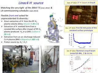
Functional specifications: Spec’s last week No final Spec’s “BEAM MEASUREMENTS FOR LINAC4 AND ITS TRANSFER LINES” EDMS Id: 1063849 (2010) LIST OF DIAGNOSTICS REQUIREMENTS (observables): • POSITION, INTENSITY AND PHASE (from BPM) • BEAM INTENSITY • BEAM PROFILE & EMITTANCE • BEAM LOSS • BUNCH LENGTH • BI/SW provides software interfaces to these observables for client applications Important points: • Re-use hardware/software as much as possible (software APIs from LINAC2/PSB systems) • Use 3MeV test-stand for proto-typing • Face-to-face discussions Lars K. Jensen BI-SW
BI Systems Date of expected initial use (3MeV test-stand ++): Faraday-cup Emittance-meter SEM-grids BCT Beam Wire Scanner Beam Position Monitor Beam Loss Monitor BTVs (?) Bunch Shape Monitor Lars K. Jensen BI-SW
Faraday cup • Scope: • Test-stand + LINAC4 • Present status: • Acquired with local oscilloscope • Wish: • Time resolved (cross-calibrated) current readout for LINAC4 source installation (2013) • Plans to be made Lars K. Jensen BI-SW
Emittance-meter • Scope: • 3MeV test-stand • Source re-commissioning • Status: • Time resolved beam profiles with HOR/VER slit control • Acquisition and control implemented (FESA/Labview/C++) • Plans: • New slits (allowing for higher energies) (Delphine’s talk) • RFQ tests early 2012 • Low-level software changes no/minimal changes for application Lars K. Jensen BI-SW
SEM-grids • Scope: • 3MeV test-stand, LINAC4 (<30MeV) • Status: • Acquisition + motor control for test-stand spectrometer SEM-Grids done (FESA/JAVA) • Time resolved profiles (~6usec) • Plans: • Acquisition/control hardware for final LINAC4 being designed (Gerrit-Jan) • Test-stand beam tests during 2012 Lars K. Jensen BI-SW
BCTs #1 • Scope: • Test-stand, LINAC4, Transfer-lines (new, old) • Status: • Proof of principle for electronics and software during 2011 • Time resolved intensity measurement • Average current & total number of charges per LN4 pulse • Plans: • Commissioning of acquisition electronics and software • New spec’s being evaluated • 5 BCT devices on 3MeV test-stand (2012) • Intensity watch-dog (interlock) • Functional specifications well advanced (combination of hardware and software for added flexibility) • EDMS: L4-CIB-ES-0003 Lars K. Jensen BI-SW
BCTs #2 • Based on comparing 2 BCT values • Which ones depend on beam destination • Two levels of interlock: • ‘Relatively low’ (OP setting): • Count number of consecutive pulses (PPM) and compare to OP threshold • If too many cycles, disable beam for next occurrence of particular cycle until OP reset • ‘Relatively high’ (OP setting): • If loss > threshold cut next cycle until OP reset (who’s allowed?) Lars K. Jensen BI-SW
Wire-scanners • Scope: • Test-stand, LINAC4 .. • Status: • HW/SW being tested • SW resembles slow ISOLDE scanners • Time resolved profiles • Plans: • Beam tests foreseen early 2012 Lars K. Jensen BI-SW
BPMs • Scope: • Test-stand, LINAC4, Transfer-lines • Status: • HW design/production on-going • Software will provide: • Position and (cross-cal.) Intensity: • Time resolved along LN4 batch @22MHz • Derived signals to be discussed • Phase with respect to the RF freq. • Being specified • Plans: • Beam tests starting 2011: • 3 BPMs on test-stand Lars K. Jensen BI-SW
BLMs • Scope: • (Test-stand), LN4, Transfer-lines • Status: • Hardware design (analogue/digital) on-going • Interlocking spec’s to be finalized • Plans: • Lab tests during Q4 2011 • Software design to start early 2012 • Will provide: • Time resolved losses (2usec) • Integral over 1msec Lars K. Jensen BI-SW
BTVs • Scope: • 3 devices in dump line (?) • 1 in new transfer-line (?) • 3 new in LBE line (?) • 4 at PSB injection (stripper foil) • Status: • Reuse hardware and software • Plans to be made when LN4 connection date is known Lars K. Jensen BI-SW
Bunch Shape • Scope: • Test-stand + LN4 • Complete system built by JINR • Status: • Will come with Labview software on PC for test-stand • Plans: • Control system integration TBD Lars K. Jensen BI-SW
Conclusions • Software design and delivery • follows test-stand schedule and hardware design and availability • Mix of planning ahead and feedback • Operational systems • deployed and tested when front-end computers become available • Standing agreement with OP • provide APIs for discussion • 3MeV test-stand • Very important for proto-typing • Decisions • VME hardware layout must be fixed soon • Some specifications missing Lars K. Jensen BI-SW