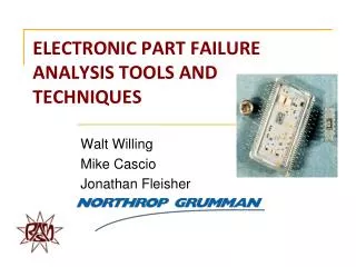
ELECTRONIC PART FAILURE ANALYSIS TOOLS AND TECHNIQUES
ELECTRONIC PART FAILURE ANALYSIS TOOLS AND TECHNIQUES. Walt Willing Mike Cascio Jonathan Fleisher. Agenda. Importance of effective Failure Analysis Basic Failure Analysis Process Failure Analysis Techniques Electrical Testing / Characterization Non-Invasive Tests Invasive Tests

ELECTRONIC PART FAILURE ANALYSIS TOOLS AND TECHNIQUES
E N D
Presentation Transcript
ELECTRONIC PART FAILURE ANALYSIS TOOLS AND TECHNIQUES Walt Willing Mike Cascio Jonathan Fleisher
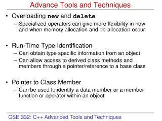
Agenda • Importance of effective Failure Analysis • Basic Failure Analysis Process • Failure Analysis Techniques • Electrical Testing / Characterization • Non-Invasive Tests • Invasive Tests • Suggestions for your own failure analysis capabilities • Understanding Electronic Part Failure Mechanisms Excerpts from the 1997 Alan O. Plait Award for Tutorial Excellence RAMS 2012 – Tutorial 8B – Willing, et al
Importance of Effective Failure Analysis • Effective root cause analysis helps assure proper corrective action can be implemented • When electronic parts fail, it’s important to understand why - the Root Cause • Accurate root cause assessment important for High Reliability systems where failures are very critical: • Implantable medical devices • Space satellite systems • Deep well drilling systems • As well commercial high production products, where the cost of a single failure mode is replicated multiple times • Common term for process of root cause determination and applying corrective action • FRACAS (Failure Reporting, Analysis and Corrective Action System) Failure Analysis is the crucial “Analysis” part of the FRACAS process RAMS 2012 – Tutorial 8B – Willing, et al
Failure Analysis - Caution“Preserve the Failure” / Prevent “RTOKs” • Failure Analysis has to be handled carefully • Assure the failure mechanism is preserved, not “Lost” due to • Carelessness • Bypassing important tests / measurements • Performing destructive analyses in an incorrect sequence. • Example: Once wirebonds are removed, the part may not be able to be electrically tested • Many parts removed for failure analysis may “Re-Test OK” (RTOK) • Possibly the wrong part was removed • Part level testing performed did not properly capture the failure mode • Subtle parameter shifts, etc. • Peculiar failure sensitivity (e.g. gain vs temperature) exists • Important to assure board level fault isolation / troubleshooting performed correctly RAMS 2012 – Tutorial 8B – Willing, et al
Top Reasons for Component Failures (1 of 3) • 1) Electrical Overstress • Transients related to test setups. • Rapid switching to full amplitude voltage / lead to inrush or high transient • Human body electrical static discharge (ESD) • 2) Solder joint failure • Poor solder joints are the most common issue related to board fabrication • Commonly responsible for latent failures due to joint fatigue driven by thermal cycling RAMS 2012 – Tutorial 8B – Willing, et al
Top Reasons for Component Failures (2 of 3) • 3) Contamination • Leads to failures stemming from corrosion or electrical leakage paths • Can rapidly destroy wire bond interconnects and metallization. • Sources of contamination • Human by-products (Spittle) • Chemicals used in the assembly process. • 4) Cracked Ceramic Packages • Ceramics are used for the majority of high reliability military and space applications • Packages are very brittle and are susceptible to cracking • Stress risers from surface anomalies • General mounting stresses (exacerbated by thermal cycling • Root causes can be traced to either design implementation or process controls • 5) Timing Issues • Intermittent failures often due to Inadequate timing margins • Through timing analysis should be part of any design when asynchronous signals are present RAMS 2012 – Tutorial 8B – Willing, et al
Top Reasons for Component Failures (3 of 3) • 6) Power Sequencing Issues • Many IC technologies susceptible to damage if core bias voltages are not applied prior to control or data input voltages • 7) Poor Design Habits • Lack of adequate derating (voltage, power, thermal) • Most common of these is due to not managing component temperature • Running parts outside their rated power dissipation specification • Leaving CMOS inputs floating • Not properly controlling resets • Low bias voltage / Step Load “Droop” RAMS 2012 – Tutorial 8B – Willing, et al
Recommended Trouble ShootingPrior to Part Failure Analysis (1 of 3) • Isolate and confirm part failure while still on the board to the extent possible • Review initial failure data • Exonerate Test Equipment and if necessary: • Use a known good reference unit to check test set-up • Confirm failure on different test set and assembly levels • Confirm the following are within spec: • Input conditions (bias, addressing, strobe, logic) • Output parameters • Take DC probe measurements on part (Use micro-clip probes if necessary) • Look at all signals with an Oscilloscope to assure no AC oscillations • Check Line-to-line & line-to-ground isolation • Lift solder joints as required to isolate part from circuit • For RF circuits, consider soldering a coax onto part before removing and confirm input/output is out-of-spec • Use connectorized measurements as much as possible. • Probe based RF measurements are typically not consistent and unreliable RAMS 2012 – Tutorial 8B – Willing, et al
Recommended Trouble ShootingPrior to Part Failure Analysis (2 of 3) • Inspect / Photograph / X-ray part on board • Perform general examination under magnification • Focus on the following: • Solder joints • Connectors • Component (cracks, exterior finish) • Foreign Object Debris (FOD) • Suspect component • Photograph guidelines • Minimum of four angles • Solder interfaces to board • Photograph each side of part • X-ray on board prior to removal as required RAMS 2012 – Tutorial 8B – Willing, et al
Recommended Trouble ShootingPrior to Part Failure Analysis (3 of 3) • Part Removal Guidelines • Review removal process if new steps are required • Cut leaded wire connections when possible to remove part • Witness removal as necessary • If heat is required to remove part • Take as much data as available, excessive solder heat may corrupt evidence RAMS 2012 – Tutorial 8B – Willing, et al
Basic Failure Analysis Techniques • Electrical Testing / Characterization • Non-Invasive Tests • Invasive (Destructive) Tests RAMS 2012 – Tutorial 8B – Willing, et al
Basic Failure Analysis Process Flow RAMS 2012 – Tutorial 8B – Willing, et al
Electrical Testing / Characterization • First FA Step - Fully Characterize Failure Mode • Test / Characterize / Look for Sensitivities • Over temperature • Voltage range • Clock speed • Perform Curve tracer assessments on all Inputs / Outputs • Compare to known good devices • Can help isolate which pin may be damaged RAMS 2012 – Tutorial 8B – Willing, et al
Non-Invasive Tests • Second FA Step - Perform Non-Invasive Tests • External Microscopic Exam / Photo • X-ray (Film, Realtime, 3D) • Fine & Gross seal tests for hermetic devices • Vacuum Bake & Retest • PIND Test • XRF X-ray Fluorescence • Acoustic tests (SAM / C-SAM) RAMS 2012 – Tutorial 8B – Willing, et al
External Microscopic Exam / Photo • Thorough external visual examination of the suspect part using a stereo microscope should be performed early in the failure analysis process • Typical inspection scopes range from 10X to 30X magnification • Magnification levels up to 100X can be employed to further examine any anomalies identified. • The following conditions should be specifically looked for: • External contamination and/or solder balls • Possibly shorting out pins on the device • Damaged leads or package seals • Seal integrity • Lead integrity • Gross cracks in the package • Corrosion • Thermal or electrical damage • Representative Photos should be taken of the part and any anomalies Crack RAMS 2012 – Tutorial 8B – Willing, et al
X-Ray - Film / Realtime / 3D • X-Ray (Radiograph) is a very powerful tool for non-invasive failure analysis • X-Ray examinations can detect actual or potential defects within enclosed packages • There are multiple types of X-Ray equipment available • Basic film X-Rays • Real time X-Ray • 3-D X-Ray • While film X-Rays can be useful, modern Real Time X-Ray provide extensive capabilities • Resolution for film X-Ray = 1 mil particle size, or bond wires down to 1 mil diameter • Limitation of film X-Ray - only one exposure level can be taken at a time • Not all characteristics can be observed at a single exposure level • Real time X-Rays typically have a resolution range from 1um to 0.4 um • Real time allows for a continuous adjustment of exposure levels and conditions, as well as real time part rotation to obtain the most revealing X-Ray view • Special digital filtering / image processing can also be used to detect possible delinations in the image not otherwise observable on the image screen • Refer to Mil-Std-883 Method 2012 RAMS 2012 – Tutorial 8B – Willing, et al
X-Ray Examinations • X-Rays allow internal part examination looking for: • Internal particles • Internal wire bond dress • Make sure the wire bonds are not touching each other or package lids • Die attach quality (voiding, die attach perimeter) • Solder joint quality for connectors • Insufficient or excessive solder • Substrate or printed wiring board trace integrity • Obvious voids in the lid seal • Foreign metallic particles within the package • Internal part orientation, etc. RAMS 2012 – Tutorial 8B – Willing, et al
Real-Time X-ray of Coaxial Connector Normal X-ray View X-ray with Image Filtering RAMS 2012 – Tutorial 8B – Willing, et al
Acoustic tests (SAM / C-SAM) • Acoustic testing is popular for finding voids / delaminations / cracks • Plastic Encapsulated Microcircuits (PEMS) • Ceramic capacitors. • Acoustic tests rely on acoustic energy transfer through the part • If there is a void, the acoustic energy is blocked, and therefore voids can be detected • The acoustic tests can also be tuned to attempt to determine the depth of any void • Acoustic tests involve either reflected acoustic energy, or transmitted energy through the part • The energy transmission medium is typically DI water • Parts to be examined need to be able to withstand exposure to water RAMS 2012 – Tutorial 8B – Willing, et al
Acoustic Scan of a Discoidal Ceramic Capacitor CSAM identified significant void Confirmed to exist via cross-sectioning RAMS 2012 – Tutorial 8B – Willing, et al
Invasive (Destructive) Tests - Last but Not Least • Internal Package Exam / DIE Exam • Cross Sectioning • Die Probing • IR Microscopic • Liquid Crystal die thermal mapping • SEM • Auger • EDS/EDX • FIB • FTIR • SIMS (TOF SIMS / D-SIMS) • TEM (transmission electron microscopy • STEM (scanning transmission electron microscopy) • ESD Testing RAMS 2012 – Tutorial 8B – Willing, et al
Microscopic Internal / Die Exam • Look for: • Damaged metal traces • Die cracks • Broken or damaged wirebonds • Typically performed using a microscope at magnifications of 100X up to 1000X • Deep UV optical microscopes can reach 16,000 X magnification and are capable of resolving 10 microns • Microscopes equipped with both dark and light field illumination are helpful, as changing the lighting conditions can help reveal issues. • Photographs should be taken to document the condition of the die and to record any anomalies Open Wire Bond Disturbed Bonds RAMS 2012 – Tutorial 8B – Willing, et al
Cross Sectioning • Cross-Sectioning is a very important means of failure analysis • Often used for: • Connectors • Printed wiring board • Substrates • Solder joints • capacitors, resistors, transformer • Semiconductors • Prior to cross-sectioning, samples are potted in a hard setting acrylic or polyester rosin • Failed item is literary cut in a cross-sectioned fashion then highly polished for detailed microscopic examination • The potted sample can be cut in half initially to find target the failure site, or the cross-section can commence at one end of the sample and then progressively cross-section up to and through the failure site. • This progressive cross-sectioning can provide a “3D” view of the failure site. • Photograph at all steps Solder Joint RAMS 2012 – Tutorial 8B – Willing, et al
Cross-Sectioning of PWB Blister area above electrically stressed signal traces caused un-expected resistance <10ohms Deformation/ Delamination due to excessive heating RAMS 2012 – Tutorial 8B – Willing, et al
Signs of Overheating of Center Trace Distorted signal trace, Evidence of high current thru trace Damage located above the trace +28V Trace maintains shape, No evidence of over-current Material appears carbonized RAMS 2012 – Tutorial 8B – Willing, et al
Scanning Electron Microscope (SEM) • SEM is an important tool for semiconductor die failure analysis, as well as metallurgical failure analysis • SEM can provide detailed images of up to 120,000X magnification • Typical magnifications of 50,000X to 100,000X • Resolve features down to 25 Angstroms • NANO SEMs can resolve features down to 10 Angstroms • With a SEM image, the depth of field is fairly large, providing a better overall three-dimensional view of the sample • SEM examinations are often used to verify semiconductor die metallization integrity and quality • Refer to Mil-Std-883 Method 2018 RAMS 2012 – Tutorial 8B – Willing, et al
Auger Electron Spectroscopy (AES) • Sample surfaces are exposed to an electron beam designed to dislodge secondary electrons (Auger electrons) • Materials identified by energy level spectra unique to each material’s valence bands • Auger useful for detecting organic materials on surfaces • Depth profiling can occur, useful to 2000 Angstroms deep Auger profile of contamination on the surface of a wire bond pad RAMS 2012 – Tutorial 8B – Willing, et al
Energy Dispersive X-ray analysis (EDS, EDAX or EDX) • EDX is a technique used along with an SEM to identify the elemental composition of a sample • During EDX, a sample is exposed to an electron beam inside the SEM • SEM electrons collide with the electrons within the sample, causing some of them to be knocked out of their orbits • The vacated positions are filled by higher energy electrons which emit X-rays in the process • By a spectrographic analysis of the emitted X-rays, the elemental composition of the sample can be determined • EDS is a powerful tool for microanalysis of elemental constituents RAMS 2012 – Tutorial 8B – Willing, et al
Energy Dispersive X-ray (EDX, EDAX, EDS) EDS maps of a Cadmium particle RAMS 2012 – Tutorial 8B – Willing, et al
Secondary Ion Mass Spectrometry (SIMS) • SIMS is a technique which can detect very low concentrations of dopants and impurities in semiconductors • By ion milling deeper into the sample, SIMS provides elemental depth profiles from a few angstroms to tens of microns • SIMS works by sputtering the sample surface with a beam of primary ions • Secondary ions formed during the sputtering are analyzed using a mass spectrometer • These secondary ions can range down to sub-parts-per-million trace levels • Advanced SIMS analyses such as Time-of-Flight SIMS (TOF-SIMS) and Dynamic SIMS (D-SIMS) provide additional means of elemental detection and resolution RAMS 2012 – Tutorial 8B – Willing, et al
Focused Ion Beam FIB • FIB uses an ion beam to microscopically mil / ablate material away to allow for cross-sectioning of semiconductor die (ion milling) • Gallium or Tungsten ion sources are used • FIB cross-sections are examined by SEM to see features such as • Die metallization construction • Pinhole in dielectrics (oxides/nitrides) • EOS or ESD damage sites • FIB cross sections are very “polished” revealing features down to 200 to 250 Angstroms • FIB can also be used to cut semiconductor metallization lines to isolate circuitry on the die, and if necessary, a Platinum ion beam can be used to actually deposit metallization creating new circuit traces • In this case, die level design changes (known as “Device Editing”) can be implemented to allow for a design “try-out” RAMS 2012 – Tutorial 8B – Willing, et al
Focused Ion Beam (FIB) FIB cross-section of a Schottky diode FIB cross-section of a MOSFET GATE RAMS 2012 – Tutorial 8B – Willing, et al
Transmission Electron Microscopy (TEM/STEM)TEM (Transmission Electron MicroscopySTEM (Scanning Transmission Electron Microscopy) • TEM and STEM use a high energy electron beam to image through an ultra-thin sample allowing for image resolutions on the order of 1 - 2 Angstroms • S/TEM has better spatial resolution then a standard SEM and is capable of additional analytical measurements • S/TEM and requires significantly more sample preparation as very thin samples need to be prepared, often using FIB techniques • S/TEM provides outstanding image resolution and it is possible to characterize crystallographic phase and orientation as well as produce elemental maps RAMS 2012 – Tutorial 8B – Willing, et al
TEM of a gold ball bond on an Aluminum pad confirmed Good Bond Intermetallics TEM analysis of a gold/aluminum interface of a wire bond Data from the TEM provided assurance that the gold/aluminum stoichiometry was correct even after extensive life aging RAMS 2012 – Tutorial 8B – Willing, et al
Suggestions for Your Own Failure Analysis Capabilities • Suggestions are provided for Failure Analysis capabilities for a typical electronics firm • Three levels of Failure Analysis capabilities are suggested • Basic • Moderate • Advanced • Beyond these three levels, one might consider using commercial failure analysis laboratories for the more esoteric capabilities such as • TEM / STEM • SIMS • Usually its more cost effective to subcontract out those types of analyses vs. establishing them in-house RAMS 2012 – Tutorial 8B – Willing, et al
Basic Failure Analysis Lab • Basic Meters (DVMMs) • Stereo Microscope (10X to 30X) (Preferably with digital camera) • Cross Sectioning Equipment • Power Supplies / Signal generator • Curve Tracer Curve Tracer showing I/V Curve Cross-Section Equipment RAMS 2012 – Tutorial 8B – Willing, et al
Moderately Equipped Failure Analysis lab • Metallurgical Microscope (1000X) (Preferably with digital camera) • Film X-Ray • SEM • Chemical Hood with De-capsulating chemicals • Die Probe Station • Liquid Crystal • Acoustic Scan Metallurgical Microscope with Digital Camera RAMS 2012 – Tutorial 8B – Willing, et al
SEM and Acoustic Testing (CSAM) Acoustic Testing (CSAM) Scanning Electron Microscope RAMS 2012 – Tutorial 8B – Willing, et al
Advanced Failure Analysis lab • Real-time X-ray • SEM/EDS • Auger Analysis System • FIB • IR Thermal Imaging • RF Test Equipment (If necessary) RAMS 2012 – Tutorial 8B – Willing, et al
Real-time X-ray Comparison Between Film & Real-time X-ray Film X-ray Real Time X-ray RAMS 2012 – Tutorial 8B – Willing, et al
Scanning Electron Microscope with EDS EDX used for Spectral Element Analysis RAMS 2012 – Tutorial 8B – Willing, et al
Focused Ion Beam (FIB) Cross-Sectioning FIB Cross-Section – Contact Windows FIB Cross-Section – MOSFET Gates RAMS 2012 – Tutorial 8B – Willing, et al
Thermal Imaging A hotspot in a CMOS gate is indicated by the liquid crystal technique at 1000X IR Thermal Imaging System RAMS 2012 – Tutorial 8B – Willing, et al
Understanding Electronic Part Failure MechanismsExcerpts from the 1997 Alan O. Plait Award for Tutorial Excellence • Five subjects covered: • Interconnects • Semiconductor elements • Passive elements • Substrates • Packages. RAMS 2012 – Tutorial 8B – Willing, et al
Purpose of Failure Mechanisms Section • Understanding common part failure mechanisms for various technologies necessary to provide effective corrective action to avoid failures Typical Hybrid, Transistor, and IC RAMS 2012 – Tutorial 8B – Willing, et al
Wire Bonds • ISSUES: • Bond placement • Wire dress • Bonding energy • Bonding temperature • Bondability • Dissimilar metals • Corrosion • Contamination • Electrical overstress Mis-Placed bonds caused shorts RAMS 2012 – Tutorial 8B – Willing, et al
Wire Bonds Poor Stress Relief • ISSUES: • Bond placement • Wire dress • Bonding energy • Bonding temperature • Bondability • Dissimilar metals • Corrosion • Contamination • Electrical overstress RAMS 2012 – Tutorial 8B – Willing, et al
Wire Bonds • ISSUES: • Bond placement • Wire dress • Bonding energy • Bonding temperature • Bondability • Dissimilar metals • Corrosion • Contamination • Electrical overstress RAMS 2012 – Tutorial 8B – Willing, et al
Wire Bonds • ISSUES: • Bond placement • Wire dress • Bonding energy • Bonding temperature • Bondability • Dissimilar metals • Corrosion • Contamination • Electrical overstress RAMS 2012 – Tutorial 8B – Willing, et al
Wire Bonds • ISSUES: • Bond placement • Wire dress • Bonding energy • Bonding temperature • Bondability • Dissimilar metals • Corrosion • Contamination • Electrical overstress Gold / Aluminum Intermatallic“Purple Plague” RAMS 2012 – Tutorial 8B – Willing, et al