Download
1 / 7
70 likes | 103 Vues
CEIS400 UML-OOAD Diagram S yntax O verview.

E N D
UML-OOAD Diagram Summary (recommended order of creation) Use Case Diagram—shows the system boundary through actors interacting with use cases and/or use case relationships defined by uses/includes or extends. Class Diagram—shows the objects that need to be coded to support the flow of events in the use case functions on the use case diagram. Ultimately, classes will become the program code (unit of code) that enables the use case functionality in the system.View of Participating Classes (VOPC)—created to reconcile use case functions to classes needed to support them; or created right after the completed use case diagram to help capture the classes needed. Then create the class diagram from the classes captured in the VOPC matrix. Either way will ensure the use cases are reconciled to the classes for a complete requirement or design. Sequence Diagram (optional)—shows the sequential instantiation of the classes need for a given flow of event in a use case, per flow of event, a.k.a. scenario. There can be multiple sequence diagrams for a given use case function because there are multiple flows of events in a given use case. State Chart (Machine) Diagram (optional)—shows the state of the attributes (properties) in a given class, per class. It is ultimately created to ensure that all operations are accounted for in a given class, accurate class design. NOTE: Create any additional UML-OOAD diagrams, as necessary.
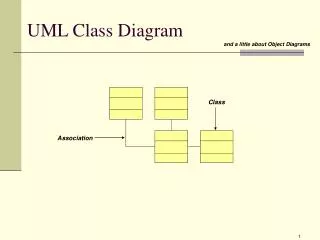
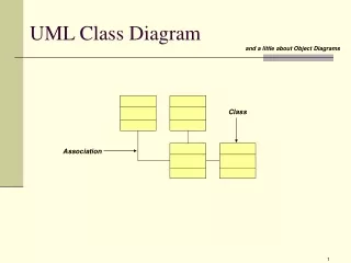
A Class An Attribute An Operation An Association Class 1 -attribute +operation () Attribute name/ derived attribute name operation name () 1..* 0..1 ______verb phrase____ Class Diagram Syntax
Sequence Diagram Syntax An Actor An Object A Lifeline A Focus of Control A Message Object Destruction anObject:aClass aMessage() x