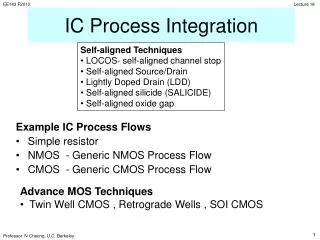
IC Process Integration
IC Process Integration. Self-aligned Techniques LOCOS- self-aligned channel stop Self-aligned Source/Drain Lightly Doped Drain (LDD) Self-aligned silicide (SALICIDE) Self-aligned oxide gap. Example IC Process Flows Simple resistor NMOS - Generic NMOS Process Flow

IC Process Integration
E N D
Presentation Transcript
IC Process Integration • Self-aligned Techniques • LOCOS- self-aligned channel stop • Self-aligned Source/Drain • Lightly Doped Drain (LDD) • Self-aligned silicide (SALICIDE) • Self-aligned oxide gap Example IC Process Flows • Simple resistor • NMOS - Generic NMOS Process Flow • CMOS - Generic CMOS Process Flow • Advance MOS Techniques • Twin Well CMOS , Retrograde Wells , SOI CMOS 1
Si3N4 CVD pad oxide Si Self-aligned channel stop with Local Oxidation (LOCOS) LOCOS Process Flow 2
FOX Self-aligned channel stop p p B+ channel stop implant dose ~1013/cm2 B Si thermal oxidation (high temperature) 3
Comment: Field Oxide Channel Inversion If poly or metal lines lie on top of the Field Oxide (FOX), they will form a parasitic MOS structure.If these lines carrying a high voltage, they may create an inversion layer of free carriers at the Si substrate and shorts out neighboring devices. The relatively highly doped Si underneath (the “channel stop”) raises the threshold voltage of this parasitic MOS. If this threshold voltage value is higher than the highest circuit voltage, inversion will not occur. Device 2 metal Device 1 SiO2 Inversion Layer p-Si 4
Comments : Non self-aligned alternative: B+ 2 1 P.R. SiO2 P+ P+ 3 SiO2 P+ P+ Si Disadvantages 1 Two lithography steps 2 Channel stop doping not FOX aligned 5
Self-aligned Source and Drain As+ poly-Si gate Perfect Alignment n+ n+ As+ Off Alignment n+ n+ * The n+ S/D always follows gate 6
Comment: Non self-aligned Alternative 1 . n+ n+ . 2 n+ n+ Channel not linked to S/D Solution: Use gate overlap to avoid offset error. . n+ n+ Stray capacitance Disadvantages: Two lithography steps, excess gate overlap capacitance 7
Lightly Doped Drain (LDD) LDD (1E17-to 1E18/cm3) Source/Drain (1E20-to 1E21/cm3) 8
CVD oxide spacer SiO2 n n n+ n+ p-sub Lightly Doped Source/Drain MOSFET (LDD) The n-pockets (LDD) doped to medium conc (~1E18) are used to smear out the strong E-field between the channel and heavily doped n+ S/D, in order to reduce hot-carrier generation. 9
LDD Process Flow using Ion Implantation n implant for LDD CVD conformal deposition SiO2 CVD SiO2 SiO2 10
Spacer left when CVD SiO2 is just cleared on flat region. Directional RIE of CVD Oxide n n n+ implant n n n+ n+ 11
RIE-based Stringers / Spacers Leftover material must be removed by overetching
Self-Aligned Silicide Process (SALICIDE) using Ion Implantation and Metal-Si reaction poly-gate TiSi2 (metal) n+ n+ Metal silicides are metallic. They lower the sheet resistance of S/D and the poly-gate 13
SALICIDE Process Flow oxide spacer SiO2 n+ n+ 14
Ti deposition Ti SiO2 n+ n+ Si TiSi2 Ti Ti Ti Selective etch to remove unreacted Ti only 15
Self-aligned Oxide Gap DRAM structure ( MOSFET with a capacitor) Thermal Oxide grown conformal on poly-I small oxide spacing < 30nm For a small spacing between poly-I and poly-II, inversion charges between MOSFET and Capacitor are electrically linked. No need for a separate n+ island. poly-II poly-I Gate oxide n+ substrate inversion charge layer poly-I MOS Capacitor poly-II MOSFET V (plate) 17
Oxide mask (dark field) Contact mask (dark field) A A Al mask (clear field) Process Flow Example : Resistor Three-mask process: Starting material: p-type wafer with NA = 1016 cm-3 Step 1: grow 500 nm of SiO2 Step 2: pattern oxide using the oxide mask (dark field) Step 3: implant phosphorus and anneal to form an n-type layer with ND = 1020 cm-3 and depth 100 nm Step 4: deposit oxide to a thickness of 500 nm Step 5: pattern deposited oxide using the contact mask (dark field) Starting material: p-type wafer with NA = 1016 cm-3 Step 1: grow 500 nm of SiO2 Step 2: pattern oxide using the oxide mask (dark field) Starting material: p-type wafer with NA = 1016 cm-3 Step 1: grow 500 nm of SiO2 Step 2: pattern oxide using the oxide mask (dark field) Step 3: implant phosphorus and anneal to form an n-type layer with ND = 1020 cm-3 and depth 100 nm Step 4: deposit oxide to a thickness of 500 nm Step 5: pattern deposited oxide using the contact mask (dark field) Step 6: deposit aluminum to a thickness of 1 m Step 7: pattern using the aluminum mask (clear field) Layout:
photoresist patterned using mask #1 oxide etchant phosphorus blocked by oxide phosphorus ions p-type Si after anneal of phosphorus implant: n+ layer p-type Si lateral diffusion of phosphorus under oxide during anneal A-A Cross-Section Step 2: Pattern oxide SiO2 p-type Si Step 3: Implant & Anneal phosphorus implant:
2nd layer of SiO2 1st layer of SiO2 Open holes for metal contacts Step 5: Pattern oxide n+ layer n+ layer p-type Si p-type Si Step 7: Pattern metal Al Step 4: Deposit 500 nm oxide n+ layer p-type Si
Thermal Oxidation ~100Å pad oxide CVD Si3N4 ~ 0.1 um Substrate Boron doped (100)Si Resistivity= 20 -cm Channel Stop Implant: 3x10¹² B/cm2 60keV Lithography Pattern Field Oxide Regions RIE removal of Nitride and pad oxide Ion Implant for Threshold Voltage control 8x10¹¹ B/cm2 35keV Thermal Oxidation to grow 0.45um oxide Wet Etch Nitrdie and pad oxide Thermal Oxidation To grow 250Å gate oxide Dope Poly-Si to n+ with Phosphorus Diffusion source LPCVD Poly-Si ~ 0.35um Generic NMOS Process Flow Description 21
Lithography Poly-Si Gate pattern RIE Poly-Si gate Source /Drain Implantation ~ 1016 As/cm2 80keV Thermal Oxidation Grow ~0.1um oxide on poly-Si And source/drian LPCVD SiO2 ~0.35um Lithography Contact Window pattern Sputter Deposit Al metal ~0.7um Lithography Al interconnect pattern RIE removal of CVD oxide and thermal oxide Sintering at ~400oC in H2 ambient to improve contact resistance and to reduce oxide interface charge RIE etch of Al metallization Generic NMOS Process Flow Description (cont.) 22
NMOS Structure Generic NMOS Process Flow Boron-doped Si 20 W-cm <100> active device ~5 mm 500mm p-Si <100> 23
P.R. nitride SiO2 Si P.R. nitride SiO2 ~0.1mm Si 24
Fox p+ p+ Fox p+ p+ 25
As+ 80keV, 1016/cm2 Resist n+ n+ Thermal oxide n+ n+ 26
intermediate oxide Al CVD oxide n+ n+ Al H2 anneal ~ 400oC (forming gas is 10% H2 and 90% N2) n+ n+ Si/SiO2 Interface States Passivation 27
A Generic CMOS Process P-well CMOS 29
Pattern mask opening For p-well implant Shallow implantation of boron Diffusion drive-in To form p-well in oxidizing ambient Remove masking oxide 30
Pad oxide growth and CVD Si3N4. Pattern field oxide regions Blanket implant of Boron for p channel stop inside p-well Protect p-well regions with photoresist. Implant Ph to form n channel stop outside p-well regions LOCOS Oxidation Thermal oxidation of gate SiO2 31
CVD poly-Si Pattern poly-Si gates and poly lines Protect ALL n-channel transistors with photoresist. Boron implantation to form source/drain of p-channel transistors and contacts to p-well 32
Protect ALL p-channel transistors with photoresist. Arsenic implantation to form source/drain of n-channel transistors and contacts to n-substrate CVD SiO2 (Low-temperature oxide) Pattern and etch contact openings to source/drain, well contact, and substrate contact. 33
Metal 1 deposition Pattern and etch Metal 1 interconnects CVD SiO2 34
Pattern and etch contact openings to Metal 1. Metal 2 deposition. Pattern, and etch Metal 2 interconnects. 35