Download
1 / 21
220 likes | 472 Vues
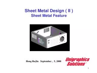
Sheet Metal Design (III). Hong RuJin September , 10, 2000. Sheet Metal Design. Sheet Metal Design (SMD) is a process-specific application that is integrated with other Unigraphics applications such as Modeling, Drafting, and Manufacturing.

E N D
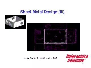
Sheet Metal Design (III) Hong RuJin September , 10, 2000
Sheet Metal Design Sheet Metal Design (SMD) is a process-specific application that is integrated with other Unigraphics applications such as Modeling, Drafting, and Manufacturing. Sheet Metal Design facilitates design for manufacturability. You can use Sheet Metal Design to create manufacturing forming/bend sequences, for unfolding and refolding the models. They can also generate accurate flat pattern data for downstream applications, such as Sheet Metal Fabrication and Sheet Metal Nesting. Application Sheet Metal Design Form / Unform model
Preferences Tools SMD General Preferences Information Note: The formulas and materials displayed in the dialog are those in ugsmd*.std file loaded in the ugiisubdirectory.
Viewing a Forming Table Process Change Body_To allow you to view the forming table for any selected body. If you have more one solid body in your part.
Information Forming Table Information on Forming Tables and Bend Sequences Information Bend Sequences
Create a manufacturing drawing Using the Bend Sequence Table
Creating and Editing a Flat Pattern Preferences SMD Flat Pattern
Smd_pip.prt Tools Flat Pattern Create Flat pattern drawing
Controlling Flat Pattern Layout Options Traverse Control refers to the method by which the system identifies the faces of a part to be flattened. If the Sheet Metal or Generic methods are used, the system automatically finds all of the faces on the same side of the part as the initial flat pattern base, or start face.If Woven or none is used, only the start face of the part is identified; no traversal of the prt occurs. Area Preserving Faces are those in which the area of the face is preserved in the flat pattern. Most of the faces in a flat pattern will be of this type. Distortion Facesare those faces which must stretch, compress, or buckle . these stretching or compressing continues through the part until the part edge is reached. A toroidal face is an example of a face that will distort upon forming
Cut Edges Projection Facesare those which you want projected to a flat pattern. An example of a face you could use for this option is a stiffening bead. The bead face is projected creating dashed lines in the flat pattern. Projection faces will not distort adjacent faces. Start Position isthe point on the start face, as given by the cursor selection point , from which all material distortion will radiate. By changing a start location you can modify the distortion profile reflected in your Woven Materials generated flat pattern. Cutting Edges lets you specify adjacent faces in the body, which will not be adjacent in the flat pattern. To separate the faces, you can use Cutting Edge and select the edges where the flat pattern will be cut.
Additional Curves use this option to select additional curves, edges, or points and add them to your flat pattern definition. Features highlights the sheet metal features which were identified as such during traversal of part. Traverse Body Traverse Body is available if a flat pattern exists for the current body. With this button you can traverse the body to find all faces on the same side of the body as the starting face. This is useful if you have automatic update turned off, and you added features to the body that need to be flattened. Once the body has been re-traversed, you must use the Update Flat Pattern to update the Flat Pattern
Sheet Metal Select the Sheet Metal traversal algorithm for parts that reflect a formable manufacturing process, and typically exhibit a uniform thickness. Generic When flat representations are required for parts where the concept of thickness does not apply, better results are obtained with the Generic algorithm. Woven Materials Use this option when you want to flatten a part made of woven materials such as composites. With this option only the selected start face is flattened. You may select additional curves and/or points to project to the flat pattern in Layout Options. None Select None when you want to flatten only the start face or a subset of faces of the body. You may then select additional faces to flatten in Layout Options. You must insure that the additional faces you select are connected somehow to the start face. Setting the Traversal Control to None will also prevent traversal of the part during automatic update. Traversal Control refers to the methods of identifying the faces of the part to be flattened. Four options are available:
Woven Materials Flattening Simple formed parts can be unrolled or unfolded easily using the automated capabilities provided by the Unigraphics Flat Pattern function. However, when the surface to be flattened is highly complex and contains multi-directional curves, simple flattening techniques are no longer effective. An exact solution for the flattening of complex surfaces requires a detailed knowledge of both the properties of the material and the forming process itself. The woven materials approach bypasses these requirements by giving particular consideration to specific forming processes and by employing solutions within the accuracy of engineering tolerances. The application handles any single surface definable by Unigraphics The basic approach the Flat Pattern function uses for woven materials is to create a grid of curves having quasi-orthogonal (near right angle) directions over the surface. Nodes on this grid represent crossing points in the weave of the woven material. The interlaced strands following these directions are called the woof (horizontal) and warp (vertical) of the material. Using a starting point you define, the woven materials algorithm traces out the paths of the strands on the surface to be unformed. For woven materials it has proven accurate to assume that the material can be "worked" onto the surface by skewing the intersection of the strands at the various nodes and keeping the distance constant along the strands between the node point.
( horizontal ) ( Vertical ) Biaxial Cloth Model Quadrilateral Material Distortion
Formed Surfaces Flattened Surfaces
Wrap Direction specifies the positive X direction of the unformed pattern relative to the original formed surface. • U parameter_X=U • V parameter_X=V • Point Tool_ X=The direction of Generic Point from the Start point on the formed surface. Origin (starting )Point for working the material to the surface can affect the shape of the resulting flat pattern. You should select the start point in a region of the surface that is relatively flat. ( the start point in a region of the surface where it is easy to position an undistorted patch of the material ). Grid Size The woven materials algorithm uses a grid size you specify during the internal process of locating the node points on the surface to be flattened. You will learn from experience what the optimum grid size is for the types of surfaces you encounter. Past studies have shown that grid sizes ranging from .1 to 1 inch give good results.
Preference Flat Pattern Annotation Flat Pattern Annotation To control and change display properties of flat pattern wireframe geometry. The display properties you can control are font, color and line width. In addition to display type control, Flat Pattern Annotation also gives the ability to interactively add text callouts to the flat pattern. Tools Flat Pattern Annotation