Download
1 / 12
140 likes | 336 Vues
Introducing a new technology: Ex ic. Read our PDF for more information. Visit http://www.extech.co.za/

E N D
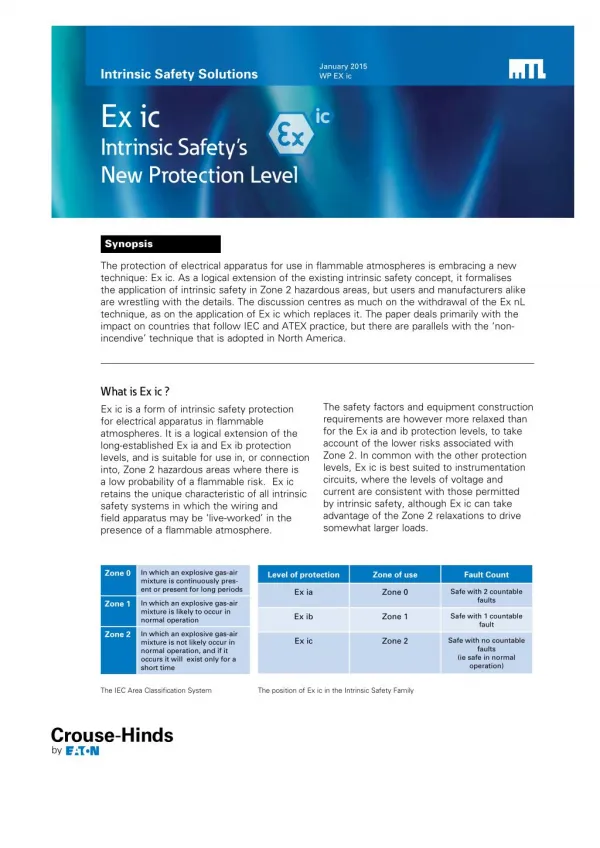
DRAFT - 08 January 2015 January 2015 WP EX ic Intrinsic Safety Solutions Ex ic Intrinsic Safety’s New Protection Level Synopsis The protection of electrical apparatus for use in flammable atmospheres is embracing a new technique: Ex ic. As a logical extension of the existing intrinsic safety concept, it formalises the application of intrinsic safety in Zone 2 hazardous areas, but users and manufacturers alike are wrestling with the details. The discussion centres as much on the withdrawal of the Ex nL technique, as on the application of Ex ic which replaces it. The paper deals primarily with the impact on countries that follow IEC and ATEX practice, but there are parallels with the ‘non- incendive’ technique that is adopted in North America. What is Ex ic ? Ex ic is a form of intrinsic safety protection for electrical apparatus in flammable atmospheres. It is a logical extension of the long-established Ex ia and Ex ib protection levels, and is suitable for use in, or connection into, Zone 2 hazardous areas where there is a low probability of a flammable risk. Ex ic retains the unique characteristic of all intrinsic safety systems in which the wiring and field apparatus may be ‘live-worked’ in the presence of a flammable atmosphere. The safety factors and equipment construction requirements are however more relaxed than for the Ex ia and ib protection levels, to take account of the lower risks associated with Zone 2. In common with the other protection levels, Ex ic is best suited to instrumentation circuits, where the levels of voltage and current are consistent with those permitted by intrinsic safety, although Ex ic can take advantage of the Zone 2 relaxations to drive somewhat larger loads. Zone 0 In which an explosive gas-air mixture is continuously pres- ent or present for long periods Level of protection Zone of use Fault Count Ex ia Zone 0 Safe with 2 countable faults Zone 1 In which an explosive gas-air mixture is likely to occur in normal operation Ex ib Zone 1 Safe with 1 countable fault Zone 2 In which an explosive gas-air mixture is not likely occur in normal operation, and if it occurs it will exist only for a short time Ex ic Zone 2 Safe with no countable faults (ie safe in normal operation) The IEC Area Classification System The position of Ex ic in the Intrinsic Safety Family
DRAFT - 08 January 2015 Ex ic Intrinsic Safety’s New Protection Level The concept of a third level of protection for intrinsic safety has existed for several decades, but only recently has it been formally adopted into the major standards systems in common use worldwide. Meanwhile, other methods of protection had filled the gap. In particular, Ex nL, a subset of the ‘safe in normal operation’ standard, Ex n, had provided a workable but somewhat loosely defined alternative. Ex nL (where the L referred to its energy- limited provenance), borrowed heavily from the published intrinsic safety ignition data to provide a method of protection in which instrumentation circuits could be live-worked in Zone 2. In North America, the ‘nonincendive’ method also delivers a roughly equivalent approach as part of its wide portfolio: the ‘nonincendive with field wiring parameters’ technique allows limited live-working in Division 2 hazardous areas. Method of Protection Ex code Permitted in: Zone 0 Zone 1 Zone 2 ma 3 3 3 Encapsulation mb 3 3 Oil immersion o 3 3 Powder filling q 3 3 Pressurisation p 3 3 da 3 3 3 db 3 3 Flameproof dc 3 ia 3 3 3 Intrinsic safety ib 3 3 ic 3 Increased safety e 3 3 nA 3 Type of protection “n” nR 3 nC 3 The IEC methods of protection and permitted Zone of use So why have things changed at last? One major factor is that Ex nL had for a long time been an uncomfortable bed-fellow with the other protection concepts that were part of the overall Ex n concept. Whereas Ex nL conformed to the relatively low voltage and current levels of energy-limitation, there were no such restrictions for the Ex nA (non-arcing), Ex nC (containment) and Ex nR (restricted breathing) techniques, which were therefore appropriate for heavy-current switchgear and rotating machines. Ex nL was more concerned with milliwatts than with kilowatts. The relevant expertise on low power circuits already existed within the IEC’s intrinsic safety committee, so as long ago as 2003, the IEC main technical committee TC31 decided to discontinue the Ex nL technique. Another influence has been the introduction of IEC ‘Equipment Protection Levels’, which formalise the application of the Ex methods to the different hazardous area Zones using the a, b and c suffices for Zones 0, 1 and 2 respectively. WP EX IC 2
DRAFT - 08 January 2015 DRAFT - 08 January 2015 Zone ATEX Category IEC Protection Level Zone 0 1 a Zone 1 2 b Zone 2 3 c ATEX Categories and IEC Protection Levels according to Hazardous Area Zone These also tie in with the ATEX ‘Categories’ 1, 2 and 3. So, in recognition that Ex nL already owed much of its provenance to intrinsic safety, the Ex nL technique was divested from Ex n and reinstated as Ex ic. Consequently, Ex ic was introduced into the 2006 version of the intrinsic safety standard, IEC 60079- 11 Edition 5.0 (and re-confirmed in the 2011 version, Edition 6.0), and the Ex nL sub- category was removed from the 2010 version of the IEC 60079-15 apparatus standard for Ex n. Other relevant intrinsic safety standards, such as the systems standard (IEC 60079-25) have also been updated to take account of Ex ic. These decisions have affected equipment manufacturers and end-users alike. From April 2013, manufacturers were no longer permitted to put ATEX-certified Ex nL apparatus onto the market. Existing Ex nL installations can remain in service, but any new projects that would previously have adopted Ex nL must now be protected by an alternative means - including Ex ic if suitably certified apparatus is available. The same, but different Ex nL and Ex ic share many underpinning principles for the explosion protection of low-power electrical apparatus. They are both based on the concept of energy- limitation, by which the levels of voltage and current present in the field wiring are incapable of causing ignition even if the circuits are shorted or broken. They both apply a unity ‘factor of safety’ Note 1 to the current level, and both are restricted to use in Zone 2. The migration to the parent technique of intrinsic safety has however created a number of detailed differences as a result of applying the broader intrinsic safety requirements (ie those created for ia and ib circuits) to Ex ic. One notable difference relates to the required separation distance between the terminals of intrinsically safe and non- intrinsically safe apparatus, for example where electronic modules and field-wiring terminals are installed onto DIN-rail in equipment cabinets. Ex nL was classified as a non-IS technique and hence its terminals required minimal separation from those of other non-IS circuits, but they were required to be separated by 50mm from IS circuits. However, Ex ic terminals are IS, so the converse is true: they must have the 50mm separation from non-IS circuits, but not from other (ie Ex ia or ib) IS circuits. Ex nL Ex ic Ex nL 1.3mm Note 2 50mm Other non-IS circuits 1.3mm Note 2 50mm All IS circuits (including ia, ib and ic) 50mm 6mm Required separation distances between terminals of Ex ic, Ex nL and other apparatus WP Ex ic 3
DRAFT - 08 January 2015 Ex ic Intrinsic Safety’s New Protection Level Other differences include: • The combinations of protection types that can occupy the same multi-core cable (Ex ic can share the same multi-core as other IS circuits, but nL cannot); • The constructional requirements of transformers; • The values of ‘creepage and clearance’ between tracks on printed circuit boards. Such changes mean that apparatus that was previously certified Ex nL may not automatically be re-certifiable as Ex ic, for example if the physical positioning of the electrical connections fall foul of the connector separation requirement. Win some, lose some Some practitioners will see the imposition of intrinsic safety’s broader requirements as a negative step, and will bemoan the loss of flexibility that accompanied Ex nL. But bringing Ex ic into the intrinsic safety fold can be argued to have a number of significant advantages: • Installation and maintenance requirements are now defined by Intrinsic Safety’s clear, internationally recognized standards and codes of practice; • More power is available for IS circuits, as a result of the unity factor of safety on current and a single active current limit; • Intrinsic Safety is consolidated as a protection method for all hazardous area Zones; • Combinations of Ex ia, ib and ic apparatus are permitted in the same system, subject to the Zone of use. • The Temperature Classification (T Class) for Ex ic is easy to define, because the apparatus is assumed to be in ‘normal operation’. A case study: Ex ic in Fieldbus Networks A common application of Ex nL has been in the design and use of FOUNDATIONTM fieldbus networks for instrumentation in the process industries. Typically, the ‘spur’ connections of field device couplers (sometimes referred to as wiring hubs) were certified as Ex nL associated apparatus, to allow the spur wiring to be live-worked when connected to suitably certified field instruments in a Zone 2 hazardous area. Historically the field instruments connected to the spurs were certified either as Ex nL apparatus, or as Ex ia or ib on the basis that the intrinsic safety construction requirements exceed those of Ex nL. This approach delivered a flexible, low cost installation, where the field instruments could be easily replaced without needing to power down the network or to declare that the area as gas-free. The idea of Ex ic is logical and relatively easy to grasp: a new level of intrinsic safety that is safe in normal operation, but where open and short-circuits in the field wiring are included in the definition of “normal”. This means that the wiring can be live-worked. WP EX IC 4
DRAFT - 08 January 2015 DRAFT - 08 January 2015 The safety of the Ex nL spurs was achieved using energy-limitation, by capping the voltage and current entering the spur circuit: the spur voltage was defined by the maximum output of the network power supply, and current limitation was provided by the individual spur short-circuit protection circuits in the device couplers. Tests performed during the certification process would have confirmed that opening or shorting the spur connections was incapable of igniting the most easily ignitable gas- air mixture, as defined by the intended Gas Group. Stored energy in the spur cables was also considered by defining appropriate cable parameters. Fieldbus Control system I/O card Fieldbus Power supply with voltage limitation Zone 2 Hazardous Area Ex nA trunk, with voltage limitation in accordance wth Ex nL Current limitation in accordance with Ex nL Ex nA [nL] apparatus Device Coupler Fieldbus spur Ex nL Ex nL or Ex i certified Fieldbus instruments With Ex nL, the fieldbus application used the power supply’s inherent voltage limitation With the migration to Ex ic, the essential voltage and current limitation still apply, except that they now have to comply with the Ex ic requirements of IEC 60079-11. At face value, the transition would appear to be relatively trivial, but the detail changes have a subtle, and in some cases radical effect on the hardware design. A particular area of interest is the fieldbus trunk (the cable that carries power from the control-room mounted power supply to the field-mounted device coupler). Under the Ex nL spur regime, the trunk wiring could be declared as Ex nA (ie non-sparking, meaning that it is designed and installed such that sparking cannot take place), but with voltage limitation in accordance with Ex nL. WP Ex ic 5
DRAFT - 08 January 2015 Ex ic Intrinsic Safety’s New Protection Level This raised few eyebrows because there was no essential incompatibility between the two Ex n techniques in this application. However, the question arises whether the trunk cable can be declared as Ex nA but with intrinsically safe (ie Ex ic) voltage limitation. Is the trunk now an intrinsically safe circuit or not? Can it be half intrinsically safe, and if so how would it be treated in terms of installation and separation from other circuits? Fieldbus Control system I/O card Fieldbus Power supply Zone 2 Hazardous Area Ex nA trunk Ex ic voltage limitation Current limitation in accordance with Ex ic Ex nA [ic] apparatus Device Coupler Fieldbus spur Ex ic Ex i certified Fieldbus instruments With Ex ic, a separate voltage limiter is inserted to avoid an ambiguous Ex nA/ic classification for the fieldbus trunk This particular point demonstrates how the looser interpretation of Ex nL permitted a real-life application, whereas Ex ic requires a more rigorous approach. As a manufacturer of field wiring components for Foundation fieldbus networks, the author’s company has considered carefully how to develop a safe and workable network with Ex ic spurs. The primary design requirements were: • To attempt to comply with the safest interpretation of Ex ic requirements, in particular where the certification organisations (notified bodies) held differing views; • To unambiguously identify the Ex method of protection invoked for each part of the network, so that the user can install and maintain it appropriately. WP EX IC 6
DRAFT - 08 January 2015 DRAFT - 08 January 2015 The resulting solution, and its comparison with the preceding Ex nL implementation, provides a useful window on how the migration to Ex ic may affect other areas of instrumentation. One particular characteristic of the fieldbus application is to move the circuitry that performs the Ex ic voltage limitation from the network power supply to a separate unit located in the field, close to the device coupler. This has the benefit of rendering the trunk entirely Ex nA in certification terms, meaning that it does not attract any requirement to separate it from other non-intrinsically safe circuits. Importantly, this avoids the need to treat the trunk wiring (and its associated terminals) as intrinsically safe where it weaves its path through the control room marshalling cabinet. Alternative solutions with the Ex ic voltage limitation in the power supply have to provide the necessary 50mm separation between the trunk terminals and those of other non-IS circuits - assuming the installer has read the details in the vendor’s instruction manual! A further benefit of classifying the trunk as Ex nA (and only nA), is that other non- intrinsically safe field devices can be connected to the trunk via a conventional device coupler, allowing a mix of Ex nA, Ex d and Ex i instruments on the same segment. This arrangement is questionable if the trunk is classified as part Ex nA, part Ex ic. Whether it was permissible under Ex nL rules is also difficult to say for certain, since the relevant installation requirements were poorly defined. Fieldbus Control system I/O card Fieldbus Power supply Zone 2 Hazardous Area Ex d or Ex nA certified Fieldbus instrument Ex ic voltage limitation Ex nA [ic] apparatus Device Coupler Fieldbus spur Ex ic Ex i certified Fieldbus instruments A benefit of defining the trunk as Ex nA is that Ex d or Ex nA field devices can also be connected to the segment WP Ex ic 7
DRAFT - 08 January 2015 Ex ic Intrinsic Safety’s New Protection Level Managing the transition As the instrumentation community adapts to the brave new world of Ex ic, other questions come to mind. Can apparatus certified as Ex nL be used in Ex ic circuits, and vice-versa? Such questions are most likely to be relevant to existing ‘nL’ installations, or to the re-use of ‘nL’ certified field instruments. New installations will be driven entirely to ‘ic’ because of the unavailability of ‘nL’ certified apparatus. However, the use of ‘nL’ apparatus in ‘ic’ systems does already have a precedent, since it is covered in the FISCO (Fieldbus Intrinsically Safe Concept) annex of the system standard IEC 60079-25. This can be extended to other fieldbus systems, and arguably also to other non-fieldbus Ex ic circuits. If the ‘nL’ apparatus parameters are well defined, it can be used. The analysis should be recorded in the system documentation. In practice, this is most likely to apply to the use of an Ex nL certified field transmitter in an Ex ic circuit. Where the safety parameters of an ‘ic’ apparatus are compatible with the requirements of the system (they may be more detailed than those of the ‘nL’ apparatus), then the ‘ic’ apparatus can be used in an ‘nL’ system. Again, the change should be justified and recorded in the system documentation. This would cover the use of an ‘ic’ field transmitter in an existing ‘nL’ installation. The details of such issues are still under discussion in hazardous area forums. For example, voices within the IEC ‘maintenance team’ for the intrinsic safety standard are arguing that the new situation is just too complicated. Their point is that the rules for Ex ic should have been much more akin to those for Ex nL: in effect, a re-naming of the technique but not a complete re-definition. Could there yet be a ‘U-turn’? Possibly, but only in the lengthy timescales needed to up-issue an Ex standard. Just to keep everyone on their toes, another important change is pending in the certification world: Ex nA will itself be withdrawn from the IEC 60079-15 standard, and replaced by a new “Ex ec” level of protection in IEC 60079-7 for ‘increased safety’ apparatus. In common with Ex ic, the use of Level of Protection ‘c’ is invoked for Zone 2, but this time it is being applied to normally non-sparking apparatus and circuits. Again, although the inherent characteristics of nA will transfer to a new level in the increased safety standard, there will be detail differences that mean existing nA apparatus may not be automatically re-certifiable as Ex ec. It is probable that the new edition of the IEC 60079-7 standard containing Ex ec will appear at the end of 2015, and become an ATEX harmonised standard possibly mid-2016. WP EX IC 8
DRAFT - 08 January 2015 DRAFT - 08 January 2015 In summary The idea of Ex ic is logical and relatively easy to grasp: a new level of intrinsic safety that is safe in normal operation, but where open- and short-circuits in the field wiring are included in the definition of “normal”. This means that the wiring can be live- worked. It is restricted to Zone 2, in which any flammable atmosphere is fleeting. Its IEC predecessor, Ex nL, embraced the same concept but was adopted with more flexibility because, unlike intrinsic safety, the overall installation requirements were less well defined. The withdrawal of Ex nL will therefore leave a gap that Ex ic may find difficult to fill, especially where manufacturers find that existing Ex nL products cannot be automatically re-certified as Ex ic. It may take some time for the dust to settle. The formalisation of the design, installation and maintenance rules that follow from the absorption of Ex ic into the broader world of intrinsic safety are however to be welcomed. It would difficult to point to ways in which Ex nL was less safe, but it was less well understood (and therefore more vulnerable to widely different interpretations) than intrinsic safety. The situation is further complicated by the fact that the standards organisations are still debating whether the technical requirements of Ex ic are too onerous - even after the new standard has been published. So it is yet possible that future versions of the intrinsic safety standard will relax the rules and move the goalposts again! WP Ex ic 9
DRAFT - 08 January 2015 Ex ic Intrinsic Safety’s New Protection Level Notes 1. The ‘factor of safety’ refers to a safety margin that is applied to the permitted current level. For a given voltage level, the published ‘ignition curves’ define the maximum current at which ignition does not occur. With intrinsic safety protection levels Ex ia and ib, the actual current is reduced by 50%; with Ex ic, no margin is applied. 2. The separation distance depends on the voltage. For Ex nL circuits defined as ‘low power’ it is zero. For up to 32V, the required separation is 1.3mm. WP EX IC 10
DRAFT - 08 January 2015 DRAFT - 08 January 2015 WP Ex ic 11
DRAFT - 08 January 2015 AUSTRALIA MTL Instruments Pty Ltd, 205-209 Woodpark Road, Smithfield, New South Wales 2164, Australia Tel: + 61 1300 308 374 Fax: + 61 1300 308 463 E-mail: mtlsalesanz@eaton.com JAPAN Cooper Crouse-Hinds Japan KK, MT Building 3F, 2-7-5 Shiba Daimon, Minato-ku, Tokyo, Japan 105-0012 Tel: + 81 (0)3 6430 3128 Fax: + 81 (0)3 6430 3129 E-mail: mtl-jp@eaton.com BeNeLux MTL Instruments BV Terheijdenseweg 465, 4825 BK Breda The Netherlands Tel: + 31 (0) 76 7505360 Fax: +31 (0) 76 7505370 E-mail: mtl.benelux@eaton.com NORWAY Norex AS Fekjan 7c, Postboks 147, N-1378 Nesbru, Norway Tel: + 47 66 77 43 80 Fax: + 47 66 84 55 33 E-mail: info@norex.no CHINA Cooper Electric (Shanghai) Co. Ltd 955 Shengli Road, Heqing Industrial Park Pudong New Area, Shanghai 201201 Tel: + 86 2128993817 Fax: + 86 2128993992 E-mail: mtl-cn@eaton.com SINGAPORE Cooper Crouse-Hinds Pte Ltd No 2 Serangoon North Avenue 5, #06-01 Fu Yu Building Singapore 554911 Tel: + 65 6 645 9888 Fax: + 65 6 487 7997 E-mail: sales.mtlsing@eaton.com FRANCE MTL Instruments sarl, 7 rue des Rosiéristes, 69410 Champagne au Mont d’Or France Tel: + 33 (0)4 37 46 16 70 Fax: +33 (0)4 37 46 17 20 E-mail: mtlfrance@eaton.com SOUTH KOREA Cooper Crouse-Hinds Korea 12F, Vision Tower, 707-2 Yeoksam-Dong Gangnam-Gu, Seoul 135-080, South Korea. Tel: + 82 2 538 3481 Fax: + 82 2 538 3505 E-mail: mtl-korea@eaton.com GERMANY MTL Instruments GmbH, Heinrich-Hertz-Str. 12, 50170 Kerpen, Germany Tel: + 49 (0)22 73 98 12 - 0 Fax: + 49 (0)22 73 98 12 - 2 00 E-mail: mtlgmbh@eaton.com UNITED ARAB EMIRATES Cooper Industries/Eaton Corporation Office 205/206, 2nd Floor SJ Towers, off. Old Airport Road, Abu Dhabi, United Arab Emirates Tel: + 971 2 44 66 840 Fax: + 971 2 44 66 841 E-mail: mtlgulf@eaton.com INDIA MTL India, No.36, Nehru Street, Off Old Mahabalipuram Road Sholinganallur, Chennai - 600 119, India Tel: + 91 (0) 44 24501660 /24501857 Fax: + 91 (0) 44 24501463 E-mail: mtlindiasales@eaton.com UNITED KINGDOM Measurement Technology Limited, Great Marlings, Butterfield, Luton Beds LU2 8DL Tel: + 44 (0)1582 723633 Fax: + 44 (0)1582 422283 E-mail: mtlenquiry@eaton.com ITALY MTL Italia srl, Via A. Meucci, 10, I-20094 Corsico (MI), Italy Tel: + 39 (0)2 61802011 Fax: + 39 (0)2 61294560 E-mail: chmninfo@eaton.com AMERICAS Cooper Crouse-Hinds MTL Inc. 3413 N. Sam Houston Parkway W. Suite 210, Houston TX 77086, USA Tel: + 1 281-571-8065 Fax: + 1 281-571-8069 E-mail: mtl-us-info@eaton.com Measurement Technology Limited, Great Marlings, Butterfield, Luton Beds, LU2 8DL, UK. Tel: + 44 (0)1582 723633 Fax: + 44 (0)1582 422283 E-mail: mtlenquiry@eaton.com www.mtl-inst.com EUROPE (EMEA): +44 (0)1582 723633 mtlenquiry@eaton.com The given data is only intended as a product description and should not be regarded as a legal warranty of properties or guarantee. In the interest of further technical developments, we reserve the right to make design changes. THE AMERICAS: +1 800 835 7075 mtl-us-info@eaton.com © 2014 MTL All Rights Reserved Publication No. WP Ex ic January 2015 ASIA-PACIFIC: +65 6 645 9888 sales.mtlsing@eaton.com