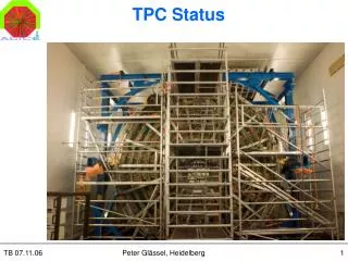
TPC DCS
TPC DCS. Pre-commissioning Final system. Pre-commissioning Hardware PVSS Supervisory Layer / FSM. HV 3 Module Iseg LV 2 PL500/F8 Temperature Monitoring 500 Sensors read-out by 18 ELMBs VHV Heinzinger incl. PLC/PVSS/FSM FEE 12 Readout Partitions (2 sectors) Laser Laser control

TPC DCS
E N D
Presentation Transcript
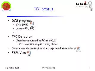
TPC DCS Pre-commissioning Finalsystem U. Frankenfeld
Pre-commissioning HardwarePVSS Supervisory Layer / FSM • HV • 3 Module Iseg • LV • 2 PL500/F8 • Temperature Monitoring • 500 Sensors read-out by 18 ELMBs • VHV • Heinzinger incl. PLC/PVSS/FSM • FEE • 12 Readout Partitions (2 sectors) • Laser • Laser control • Mirror control • Gas system • GWG / IT-CO U. Frankenfeld
Commissioning Hardwarestand alone • Drift Velocity Monitor • FEC cooling • Pulser PS U. Frankenfeld
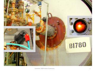
Electronics Cooling System After water accident All sensitive area at under pressure ΔT ~ 1 K in each sector System has been optimized for safe operation even with large leaks (silicon hose) Pressure in the reservoir: > 350 mbar, < 380 mbar Interlock: 400 mbar Interlock action: turns circulation pump off generates alarm starts procedure to turn off electronics Pre-commissioning Cooling System(concept similar to final set-up) 1 4 2 3 U. Frankenfeld
1 2 3 4 U. Frankenfeld
Water spill from under pressure system? Vacuum Pump Squeezed hose Air bubbles Reservoir Sector Over pressure Circulation Pump U. Frankenfeld
Bypass (or 2nd sector) needed to limit max pressure at sector Flow: 10 l/min Hydrostatic pressure in sector 13 Pressure (single sector) Bypass Valve in serial U. Frankenfeld
Pressure drop in Sector U. Frankenfeld
Summary Cooling • Save operation with two sectors (opening of one hoses tested) • Hoses • Bypass (one sector) • Alarm settings • Visual alarm • Triggered by flow meter • System stops flow in case of alarm • Final system: • One pressure sensor at the inlet of each cooling sector • Signal read-out by DSS system-> used as interlock to stop circulation pump U. Frankenfeld
500 calibrated PT1000 18 ELMBs Display with color code and auto scaling Trending of selected probes Display of history data Temperature Sensors U. Frankenfeld
Sensor Calibration U. Frankenfeld
Temperature monitoring U. Frankenfeld
History U. Frankenfeld
Trending Δ T ~ 1K U. Frankenfeld
Pre-commissioning Summary • Cooling • Additional presure sensores -> Interlock • Temperature Monitoring • Working • LV • Pl500 F8 used +ok • HV • Control software for Iseg: ok • Combination PS – Chamber with serial resistor • FEE -> next talk • Connection Intercom Layer -> PVSS installed • Needs to be tested and debugged U. Frankenfeld
Pre-commissioning Summary • VHV • ok • Laser • Laser control and tracker used • Frame grabber for cameras • Mirror control tested • Gas system • Operated very well • Updates/bug fixes during pre-commissioning • Drift Velocity Monitor • Put in operation • Pulser PS • Operated manually • Next step • Installation + Commissioning U. Frankenfeld
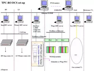
TPC(1) 1 2 2 216 1 2 18 18 1 6 12 10 288 108 12 2..4 1 216 1 72 500 1 06/03/13 [FSM?] Database(s) PVSS II PVSS II PVSS II Control room (ACR) OPCclient DIMclient User interface Ethernet CR3 CR3 CR4-Z08 CR3 CR3 CR3 PVSS II PVSS II PVSS II PVSS II PVSS II PVSS II OPC client Modbus/TCP OPC client DIMclient Virtual Serial OPC client ISEG OPCserver Wiener OPCserver E E E ELMB OPCserver CR3 [FED] PCI-CAN DIMserver PCI-CAN C E C CR4-Z08 DIMclient PLC C ACC E ACC S CR4-Y08 CR4-Z08 ISEG Heinzinger ACC UX-C08/D16 Eth.-RS232 UX-A,B,C UX-C/D PS Calibr.pulser Wiener Ethernetswitch Gatingpulser E HV LV ELMB HV ELMB DDL Chambers Chambers Chambers,detector RCU HVrod HVrod Chambers DIMsrv High Voltage Low Voltage Temp. Monitor FEE Very High Voltage VHV Curr. Monitor Pulser system
TPC(2) 1 1 4 18? 40 06/03/13 Ethernet CR3 SG2 CR3 CR3 PVSS II PVSS II PVSS II PVSS II Modbus/TCP DIMclient DIP DIM client E E RS232 CR3 E [Vision] DIMserver/filesystem [GWG] GasPVSS Video In [TS/CV] SG2 CR3 PLC [Motion][Laser] DIMserver Heinzinger TS/CVSCADA virtual serial SG2 Video Analysis DIMsrv Gas LHut UX-C UX-C Eth.-RS232 PLC PLC LHut LHut Spectronlaser Mirrorcontrol CR5 Gas CoolingPlant (ch) CoolingPlant (TS) Mirror adj. Trig Board(STAR) Mirror adj. Videocameras Chambers,detector HVrod ThermalScreen(s) Detector Laser calibration system. Chamber Cooling VHV rod Cooling Thermal Screen(s) Gas system Drift velocity mon.
Hierarchy overview TPC Detector GAS ROC FC FERO TEMP Screen LASER D mon GasD GasD CO2 RCool VHV SSW Cone ROC TSen ....... +500x … HV Gating ESC CalibP ESC LaserC MirrorC 36x ....... IROC OROC MISC GPulser PS FED LV ECool CPulser PS Crate PS Calib Image Mirror Ch Ch Ch Ch Ch RCU Ch Ch ....... ....... ....... ....... ....... ....... ....... ....... 36x (2x) 36x 10x 98x ??x 6x 72x ??x
Hierarchy overview Prototype TPC Prototype in progress Detector GAS ROC FC FERO TEMP Screen LASER D mon GasD GasD CO2 RCool VHV SSW Cone ROC TSen ....... +500x … HV Gating ESC CalibP ESC LaserC MirrorC 36x ....... IROC OROC MISC GPulser PS FED LV ECool CPulser PS Crate PS Calib Image Mirror Ch Ch Ch Ch Ch RCU Ch Ch ....... ....... ....... ....... ....... ....... ....... ....... 36x (2x) 36x 10x 98x ??x 6x 72x ??x