BE-ABP-LAT
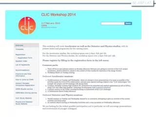
BE-ABP-LAT. BE-ABP-LAT. Infos & statistics. 306 participants (31 countries), about one third from CERN 187 talks, 156 speakers 32 talks by LAT members. BE-ABP-LAT. Monday afternoon: Plenary session in the Globe. BE-ABP-LAT.

BE-ABP-LAT
E N D
Presentation Transcript
BE-ABP-LAT • Infos & statistics • 306 participants (31 countries), about one third from CERN • 187 talks, 156 speakers • 32 talks by LAT members
BE-ABP-LAT Monday afternoon: Plenary session in the Globe
BE-ABP-LAT Tuesday: Parallel Working Groups sessions (accelerator + physics & detectors) Main flows: Design& System tests, X-band Special: Power & Energy studies, PACMAN
BE-ABP-LAT Wednesday: Parallel Working Groups sessions (accelerator + physics & detectors) Accelerator plenary: CTF3/CERN based future facilities Parallel & joint sessions Design, System Tests and Xband Special: EuCARD2 (RF)
BE-ABP-LAT Wednesday: High Gradient Day X-FELs, Medical & Industrial applications of Xband Parallel: Low Emittance Ring collaboration
BE-ABP-LAT Friday:Accelerator Plenary + CLIC Collaboration Board
BE-ABP-LAT P. Skowronski – CTF3 Report and Plans
Motivation R. Corsini – Beyond CTF3 • CTF3 went well beyond its initial task of demonstrating CLIC two-beam scheme feasibility • Has a well established scientific program until end 2016 • Definitely want to stop CTF3 after that (limited resources) need to develop a plan • Additional considerations: • Initial plan was to evolve gradually towards DB front-end, shifting resources from CTF3 to the front-end, however this is now delayed • No local (CERN) real testing capability with beam (diagnostics and components) beyond 2016 • In present plan, no way to test new generation modules with beam
List of potential options (non exhaustive…) • Shut-down CTF3 completely and re-use for other scopes the buildings and whatever hardware may be requested (3 GHz power stations, magnets, power supplies…) • Refurbish CTF3 as part of new lepton injection chain at CERN (potential interest for SPS damping ring tests, plasma wake-field experiments in AWAKE, future lepton accelerators…) • Keep CALIFES probe beam injector running as a generic test facility for testing diagnostics and other components. May include additional X-band powering. • House the DB Front-End in CTF3 (CLEX or Linac?). Possible option: plug Front-End before the CTF3 linac. • Extend CTF3 running limited to first part of the linac,for X-band beam loading tests. Option: use dog-leg for X-band RF production - testing? F. Tecker W. Farabolini S. Doebert R. Corsini – Beyond CTF3
Options R. Corsini – Beyond CTF3 Lepton Injector Chain Dog-leg CALIFES facility DB Front End
Y. Papaphilippou– Damping ring performance and experimental tests, including potential at CERN (SPS)
Y. Papaphilippou– Damping ring performance and experimental tests, including potential at CERN (SPS)
Y. Papaphilippou– Damping ring performance and experimental tests, including potential at CERN (SPS)
Experiments at FACET • A. Latina - • Main beam performance tests in FACET and existing or future FELs (FELs based on Xband technology) • FACET (Facility for Advanced Accelerator Experimental Tests) is a User Facility at SLAC National Accelerator Laboratory. • The first User Run started in spring 2012 with 20 GeV, 3 nC electron beams. • The facility is designed to provide short 20 μmbunches and small (20 μm wide) spot sizes • Experiments at FACET: • Plasma wake field acceleration, dielectric structure acceleration, Smith-Purcell radiation, magnetic switching, terahertz generation … • E-211: Beam-Based Alignment
A. Latina - Main beam… Emittance Growth andDispersion-Free Steering Incoming oscillation/dispersion is taken out and flattened; emittance in LI11 and emittance growth significantly reduced. Emittance at LI11 (iteraton 1) X: 43.2 x 10⁻⁵ m Y: 27.82 x 10⁻⁵ m Emittance at LI11 (iteration 4) X: 3.71 x 10⁻⁵ m Y: 0.87 x 10⁻⁵ m S19 phos, PR185 : After 3 iterations Before correction After 1 iteration
SLC emittance Sectors 02-03 • A. Latina - Main beam… Golden orbit: εy=4.4 μm εy[10-5 m] εy=2.0 μm 1. We spoiled the emittance 2. We applied WFS Lower emittance achieved in S04! Emittance growth (before after) • Δεy=2.4 ± 0.1 μmΔεy=0.0 ± 0.1 μm (before WFS) (after WFS)
Beam Physics challenges at X-band XFEL • Emittance preservation (longitudinal and transverse) • Misalignments, dynamic effects, ISR, CSR • Beam-based alignment: DFS, WFS, …, tuning bumps • Bunch-to-bunch effects • Stray fields • Diagnostics • Fast transverse and longitudinal bunch measurements • Feed-back and feed-forward loops • Fast orbit, dispersion, wake-fields correction • Phase-energy stabilization: LL-RF but not only • Ground-motion counteraction • Performance tests of accelerator components and technologies • X-band RF, industrialization, test stands, … • A. Latina - Main beam…
Simplified Parameter Diagram Parameter Routine Luminosity, RF+beam constraints Lstructure, f, a1, a2, d1, d2, G Idrive Edrive τRF Nsector Ncombine fr N nb ncycle E0 fr Ecms, G, Lstructure Two-Beam Acceleration Complex Lmodule, Δstructure, … Main Beam Generation Complex Pklystron, … Drive Beam Generation Complex Pklystron, Nklystron, LDBA, … D. Schulte, CLIC Rebaselining Progress,
Summary on the high-power RF constraints RF breakdown and pulsed surface heating constraints used for CLIC_G design (2007): • Esmax < 250 MV/m • Pin/Cin·(tpP)1/3 = 18 MW·ns1/3/mm • ΔTmax(Hsmax, tp) < 56 K Optimistic RF breakdown and pulsed surface heating constraints for BDR=10-6bpp/m: • Esmax·(tpP)1/6< 250 MV/m · (200ns)1/6 • Pin/Cin·(tpP)1/3 < 2.8 MW/mm · (200ns)1/3 = 17 [Wu] • Scmax·(tpP)1/3 < 5 MW/mm2 · (200ns)1/3 • and • ΔTmax(Hsmax, tp) < 50 K Since new year in database • Depending on degree of our optimism a safety margin has to be applied. • Varying RF constraints in the optimization how much money one can save by being optimistic. D. Schulte, CLIC Rebaselining Progress, February 2014 A. Grudiev
Cost and Power • Not all cost is in cost model • Only the varying part for which we established the cost • Cost model • Drive beam (Robert Corsini, Igor Syratchev,DavideAguglia) • Main linac (AlexejGrudiev) • Civil engineering and infrastructure (Philippe Lebrun) • Cost for 500Gev based on CLIC_G is consistent with CDR (4.5 a.u.) • Some cost savings identified in rebaselining • Conventional facilities for second drive beam accelerator (Philippe Lebrun) • Higher power klystrons for drive beam accelerator (Igor Syratchev) • Revised modulator cost (DavideAguglia) • No electron pre-damping ring required (YannisPapaphilippou, Steffen Doebert) • Power model (Bernard Jeanneret) • Made some update D. Schulte, CLIC Rebaselining Progress, February 2014
Cost vs. Bunch Charge CLIC_G parameters are no solution Train can only have 245 bunches not 312 Cannot reach 1034cm-2s-1 at 350GeV with 50Hz repetition rate 6.5 L=0.5x1034cm-2s-1 L=1x1034cm-2s-1 L=2x1034cm-2s-1 S=1.1 Cost [a.u.] Luminosity goal significantly impact minimum cost For L=1x1034cm-2s-1 to L=2x1034cm-2s-1 costs 0.5 a.u. 2.5 2.5 0 12 N [109] D. Schulte, CLIC Rebaselining Progress, February 2014
Impact of RF Constraints 5.5 S=1.0 L=1.1 L=1.2 Safety factor S: Structure can tolerate S-times the nominal gradient for the full pulse length L=1034cm-2s-1 Cost [a.u.] 10% safety in gradient cost about 0.1 a.u. 2.5 0.18 0.08 a/l D. Schulte, CLIC Rebaselining Progress, February 2014
Conclusions • We have a cost model for main linac and drive beam complex including civil engineering and infrastructure • Injectors are being worked on • Adjusted RF limitations to experimental results • CLIC_G cannot sustain the pulse length from the CDR • Minimum cost for gradient margin is 0.1 a.u./10% • Minimum cost of doubling luminosity from 1034cm-2s-1 is 0.5 a.u. • If we pick one structure the gradient is still aa free parameter • Can change the safety margin by adjusting the beam and RF pulse parameters • Can adjust to RF testing results • But all other systems will have to redo work • And still some additional cost will occur • No safety margin at 3TeV appears possible with G=100MV/m • Do klystrons in more detail • Need to define the staging strategy D. Schulte, CLIC Rebaselining Progress, February 2014