BE/ABP-SU/
BE/ABP-SU/. Shimming test results for V-shaped support of Epucret girder DB02E Metrology lab, 31 st of may,2012. BE/ABP-SU/. Index. Introduction Fiducialisation Tests Initial measurements 1 st test: shimming 2 nd test : repeatability Conclusion. BE/ABP-SU/. Introduction.

BE/ABP-SU/
E N D
Presentation Transcript
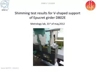
BE/ABP-SU/ Shimming test results for V-shaped support of Epucret girder DB02EMetrology lab, 31st of may,2012
BE/ABP-SU/ Index Introduction Fiducialisation Tests Initial measurements 1st test: shimming 2nd test: repeatability Conclusion
BE/ABP-SU/ Introduction After machining of V-supports which equip the Epucret girder DB02E, the dimensional control found location defaults 10 times higher than the tolerances. The V-support adjustments were planned by the design, so we wanted to test the performance of this shimming by a test in a CMM. We chose to test the shimming on the ⌀27 V-support because it only supports beam tube: no critical tolerance. All the results are available in a report and in an Excel file (EDMS n° 1221024).
BE/ABP-SU/ Fiducialisation Dimensional control and fiducialisation of the Epucret girder DB02E in the Olivetti CMM (± 6 µm at 3σ), last April (EDMS n°1209791). Coordinate system based on reference planes.
BE/ABP-SU/ Fiducialisation The tolerances about the location of V-support centres were ±0.005 mm. Location defaults are mainly along vertical direction (up to 49 µm).
BE/ABP-SU/ • Tests • Initial measurements • Session 0 • Locations determined by metrological measurements are analysed by “best fit” calculations performed under Spatial Analyser (change of coordinate system is based on the 3 fiducials). • Obtained results are comparable to fiducialisation measurements (within the CMM tolerances of ±6 µm).
BE/ABP-SU/ • Tests • 1st test : shimming • In the following, the presented results come from “best fit” calculations to allow to compare results to Session 0. • Session 1 : • Shimming of V-support: • -0.05 mm along X (laterally to girder, add of a shim), • + 0.05 mm along Z (vertically, add of a shim). • Good results, just a lateral default less than -0.01 mm.
BE/ABP-SU/ • Tests • 1st test : shimming • Session 2 : • The 2 shims were removed (return to initial status of Session 0) OK. • Session 3 : • Add of the 2 shims (return to status of Session 1). • No problem along vertical direction but the lateral default is about -0.035 mm along X.
BE/ABP-SU/ Tests 1st test : shimming How this kind of default can appear? Instead of vertical fixation, the stress applied by the lateral tightening could move the V-support centre (lever arm effect). We tried to control the torque in the following tests.
BE/ABP-SU/ • Tests • 1st test : Repeatability • Session 4 : • This session of measurements is just a control after a new positioning of the girder in the CMM: the shimming configuration is always the same (like for Session 3). Results are comparable to Session 3. • In next sessions, the presented results come directly from CMM (fiducials are not measured again).
BE/ABP-SU/ • Tests • 1st test : Repeatability • Session 5 : • All screws were unscrewed and the side screw was tightened with a torque of 4 N.m (with a dynamometric key). • The default decreased a little along X but it is always about -0.025 mm. Vertically the default reach the CMM tolerance limit. • Session 6 : • Following the same procedure, the torque is now 6 N.m. • The transversal default increased but not along Z.
BE/ABP-SU/ • Tests • 1st test : Repeatability • Session 7 : • After screwing with a torque of 8 N.m the default along X increased again and it is about – 0.045 now. • The solution of the lateral shimming, with a lever arm that generates a displacement of the V-support centre, definitely does not seem to be a reliable solution. • In next sessions, is presented an another procedure tested to try to remove the lever arm effects.
BE/ABP-SU/ • Tests • 1st test : Repeatability • Session 8 : • We tried to maintain the V-support to the lateral contact area by a clamp. The clamp is removed after the tightening of upper screws. • In the figure, the applied stress is symbolized by the red arrow: no lever arm now. The result is very different from previous: the default along X is about what we can expect without any shim! This value proves that with the side screw, the support was not properly pressed against the reference surface. We checked the repeatability of this technique by a new operation.
BE/ABP-SU/ • Tests • 1st test : Repeatability • Session 9 : • Like for Session 8, we used a clamp and followed the same procedure. • The vertical default seems to be repeatable. But the default along X increased about 0.015 mm: we concluded that this technique doesn’t allow a repeatable positioning of the V-support.
BE/ABP-SU/ Conclusion • The shimming along the vertical direction provides expected and repeatable results. Laterally, the tightening of the screw occasions defaults and a lake of repeatability. This phenomena is due to a lever arm effect. • On the girder, the defaults were mainly along the vertical direction. • Several possibilities are possible : • Try to adjust all the V-supports along the vertical direction risk of damaging the lateral adjustment and at least 5 days of work (cf. D. Pugnat). • Try to machine again the V-supports on the new AP machine fiducialisation and dimensional will have to be performed again. • We can consider that the location defaults are acceptable for a mock-up Ok for PETS but on this girder, it was decided to align 2 BPM on ⌀99 V-Supports (the vertical default on these 2 V-supports is about 50 µm).