Automotive Charging Systems for Efficient Vehicle Maintenance
Delve deep into the world of automotive charging systems, from induced voltage to AC charging systems, and learn about the components, operation, and maintenance of alternators and voltage regulators.

Automotive Charging Systems for Efficient Vehicle Maintenance
E N D
Presentation Transcript
CHARGING SYSTEMS • Induced Voltage • AC Charging Systems • Preliminary Checks • AC Generator Service • Converts Mechanical Energy into • Electrical Energy
INDUCED VOLTAGE • 3 Stationary Windings (stator) • Rotating Claw Shoes (rotor) • 12 Volts – 300 Volts Out • normal output 13-15 volts
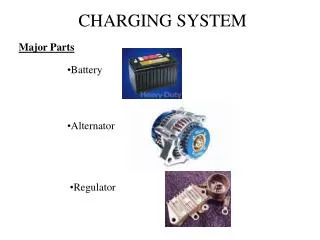
AUTOMOTIVE CHARGING SYSTEM • Purpose: • (1) Provide electrical power to the vehicle while the engine is running • (2) Charge the battery • Components: Alternator, Voltage Regulator, Wiring, Indicator, Drive Belt
ALTERNATOR COMPONETS • Terminals • Slip Rings • Cooling Fan • Belts • Rotor • Stator • Housings/ Frame • Shaft & Bearings • Drive Pulley & Fan • Diodes • Regulator
STATOR Stator is stationary Does not move Electricity is induced in the stator
ROTOR Rotor Rotates-spins Magnetic field is made in ROTOR 2 pole shoes N and S Windings Slip rings
SLIP RING END FRAME BAT terminal hot at all times
ALTERNATOR OPERATION • Three items necessary to produce current flow • 1- Conductors (stator) • 2- Magnetic Field (rotor) • 3-Motion (belt drive from crankshaft)
Alternator Operation • DC Rectification • Half Wave • Full Wave • Voltage Regulation • Sensing Voltage • Field Circuits
CONVERTING AC to DC • Alternator produces AC due to north and south magnet • Diode blocks current flow in one direction converting AC to DC • Current flow is DC at battery terminal
VOLTAGE REGULATION • Integral Regulator • Uses Transistors and a Zener Diode • Controls current to the Field Winding in the Rotor • Low Voltage On • High Voltage Off
Electronic Regulators • Integrated Circuit Voltage Regulators • Fail-Safe Circuits • Computer Regulation
Indicators • Indicator Lights • Voltmeter • Ammeter
Basic Checks • Safety Precautions • Inspection • General Tests
General Tests • Voltage Output Test • Current Output Test • Regulator Bypass Test • Oscilloscope Checks • Circuit & Ground test
ALTERNATOR LAB • Disassemble alternator • Learn all parts • Pass instructor’s quiz • Learn operation • Pass instructor’s quiz • Reassemble alternator