Analysis of 100GHz Antenna Arrays: Characteristics and Orientation Patterns
This study explores the characteristics of 100GHz antenna arrays, focusing on the orientation and wiring configurations of various elements. The antennas analyzed include horn and lens types, each with specific dimensions, gain, and effective area. The far-field patterns for multiple array orientations at various angles are detailed, highlighting performance outcomes. Various factors impacting efficiency, including ohmic losses and air/dielectric interface losses, are also discussed. This research will contribute to the optimization of high-frequency antenna applications.


Analysis of 100GHz Antenna Arrays: Characteristics and Orientation Patterns
E N D
Presentation Transcript
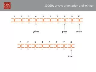
100GHz arrays orientation and wiring 1 2 3 4 5 6 7 8 9 10 yellow green white 1 2 3 4 5 6 7 8 blue
100GHz array far field center of array 1 2 3 4 5 6 7 8 9 10 angle 47.5o 6o 6o 47.5o 38o 28.5o 17.5o 28.5o 17.5o 38o Far field pattern of the 5 (left) array elements
100GHz antennas’ characteristics • Horn antenna • (diameter=2cm (dm), length= 5.5cm (L)) Gain = 295 = 24.27 (dB) Aeff = 211.3mm2 => D = 8.2mm • Lens antenna Gain = 335.7 = 25.27 (dB) Aeff = 240.5mm2 => D = 8.75mm Including losses: Ohmic:10%, Air/dielectric interface:30% , Back (air) radiation: 9%
Different diode areas responsivity response A = 0.43 , Area = 0.31mm2 A = 0.38 , Area = 0.28mm2 Old detector (A=4.14)