Download
1 / 21
210 likes | 339 Vues
Mean altitude of TEC J-L. Vergely J. Boutin P. Spurgeon ICM, Barcelona, 16/17 May 2013. Introduction. -> Faraday rotation depends on TEC altitude (not only on TEC amplitude). Possibility to give constraints on the TEC altitude ?

E N D
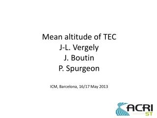
Mean altitude of TECJ-L. VergelyJ. BoutinP. SpurgeonICM, Barcelona, 16/17 May 2013
Introduction -> Faraday rotation depends on TEC altitude (not only on TEC amplitude). • Possibility to give constraints on the TEC altitude ? • Meaning of TEC altitude ? (electronic density is a layer with non nul width)
Thin layer assumption smos smos Los1 Los2 Los1 Los2 Tec layer Htec ≈ 450 km TEC(lat,lon) TEC(lat,lon) From los1 and los2 → 2 independent TEC estimation at the same place : should be the same
Htec estimation ? low sensitivity Shift between los1 and los2
Prior effect A3 sensitivity to the TEC x3 from 42° to 57°
Thin layer case smos Los1 Los2 Tec layer Htec ≈ 450 km TEC(lat,lon) TEC(lat,lon)
Thin layer case smos Los1 Los2 Tec layer Htec ≈ 300 km TEC(lat,lon) TEC(lat,lon)
Application : method • Minimisation of the dispersion close to the strong TEC gradients : cost function(Htec) = sum(variance(TEC)) • Sensitivity depends on the incidence : application of a weight depending on the A3 sensitivity to the TEC • Using 10 orbits
Application : results Cost function Best Htec Median(Htec) = 390 km Htec = 500 km
Limits of the thin layer assumption TEC=α.∫Ne(r)dr if one considers that B is constant along the line of sight. With SMOS, various angles of observation : Lines of sight Earth surface Spacecraft positions TOMOGRAPHY
Tomography Inversion of TEC(A3)=α.∫Ne(r)dr : retrieve Ne(r) from TEC(A3). Ill conditioned problem : Bayesian approach with prior. Linear problem. But positivity of the solution shall be imposed. Linear becomes non linear.
Tomography results RESULT PRIOR Chi2 too large
Prior dependence Shift in altitude and latitude Chi2 after convergence
Conclusions • A first analysis shows that the mean altitude of electronic layer is about 390 km • Electronic density seems not located always at the same altitude along the orbit • Tomography depends on the prior and shows that altitude varies with latitude • Electronic density shows the same behavior on the border of the hot spot -> variation of B according to the latitude and the altitude ?
A3 sensitivity to TEC No possibility to retrieve TEC here ! (L.O.S perp. to magnetic field) St3 is the most sensitive to TEC Pacific descending orbits A3 sensitivity to the TEC x3 from 42° to 57°