Using MFIX to Solve Multiphase Flow Problems: a tool for better understanding fluidization processes
Using MFIX to Solve Multiphase Flow Problems: a tool for better understanding fluidization processes. Janine Galvin U.S. Dept. of Energy, National Energy Technology Laboratory, Albany, OR 97321 PNNL, November 28th, 2011. Thanks to Sofiane Benyahia (NETL) and Sreekanth Pannala (ORNL).

Using MFIX to Solve Multiphase Flow Problems: a tool for better understanding fluidization processes
E N D
Presentation Transcript
Using MFIX to Solve Multiphase Flow Problems: a tool for better understanding fluidization processes Janine Galvin U.S. Dept. of Energy, National Energy Technology Laboratory, Albany, OR 97321PNNL, November 28th, 2011 Thanks to SofianeBenyahia (NETL) and SreekanthPannala (ORNL)
NETL Motivation Computational Science Division Various Computational Modeling Scales Goal Atoms – Molecules Develop and apply simulation and visualization tools for designing/analyzing zero-emission fossil energy plants. Particles Approach Integrate experimental and computational sciences at multiple scales, to generate information beyond the reach of experiments alone Unit Ops Benefits Speeds design, reduces risk, and saves money Plant
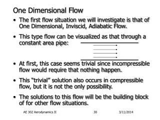
Outline • Brief overview on • multiphase flows (challenges/issues) • modeling approaches to multiphase flows & CFD • MFIX & sample applications • Hands on Work • code installation and general CFD steps • example 1: pipe flow • simulation setup (mfix.dat) • code compilation (mfix.exe) • post processing (paraview) • quick overview of MFIX solver (theory and numerical technique) • example 2: bubbling bed • example 3: spouted bed combustor Coarse Goal: Setup cases and carry out simulations with different levels of difficulty
Outline • Brief overview on • multiphase flows (challenges/issues) • modeling approaches to multiphase flows & CFD • MFIX & sample applications • Hands on Work • code installation and general CFD steps • example 1: pipe flow • simulation setup (mfix.dat) • code compilation (mfix.exe) • post processing (paraview) • quick overview of MFIX solver (theory and numerical technique) • example 2: bubbling bed • example 3: spouted bed combustor Coarse Goal: Setup cases and carry out simulations with different levels of difficulty
Overview Multiphase Flows What is Multiphase Flow? Fluid flow consisting of more than one phase or component – separation of scale above molecular level Pneumatic Transport Multiphase Flow in Industry Industry: Chemical, petrochemical, metallurgical, environmental, energy, etc Fluidized Beds Devices: fluidized beds, pneumatic transport, risers, cyclones, etc (see end of presentation) Multiphase Flow in our Environment Snow, avalanches, mud slides, debris flows, etc Chemical Process & Energy Industries
General Characteristics • Classifications of fluid flow • viscous/inviscid • compressible/incompressible • steady/unsteady • laminar/turbulent • Single-phase/multiphase • Challenges of mulitphase flow • Spatio-temporal variations • Arbitrary particle shape • Particle-particle interactions • Particle interactions with turbulence Need to model and predict detailed behavior of these flows
Reactor Design The objective of reactor design is to create the right conditions for reactions. The temperature and reactant species distribution, appropriate residence time and removal of products must be considered. Including the effect of a catalyst may be necessary. A comprehensive understanding of all the competing and interacting mechanisms is required to arrive at better designs and improved processes. In particular, gas-solids reacting flows involve, not only complex interactions of granular materials with gas flow, but also phase-change, heterogeneous and homogeneous reactions, heat and mass transfer. Moreover, the spatial and temporal scales may vary over many orders of magnitude. Thus modeling gas-solid reacting flows requires the integration of the best physics and chemistry models from various science and engineering fields with the most advanced computational algorithms. These algorithms must be scalable to large high-performance computers in order to bear on this important topic. Except from preface of an Edited Book on “Computational Gas-Solids Flows and Reacting Systems: Theory, Methods and Practice,” May, 2010, Eds. S. Pannala, M. Syamlal and T. O’Brien,
Multiphase Flow Modeling Approaches Continuum (Eulerian) Discrete particle (Lagrangian) Average out details of flow field around particles and individual particle collisions • Track interacting particle motion for all particles Pros/Cons + Computationally cheap – single equation of motion for each particle phase - Averaging process gives rise to unknown terms requiring constitutive relations • -Computationally intensive • +“Straightforward” to incorporate physics
Multiphase Flow Modeling Approaches Resolved Bubbles Molecular Dynamics Two-Fluid Resolved Particles Under-resolved discrete particle Van derHoeff et al. , Annual Review of Fluid Mechanics, 2008
Multiphase Flow Modeling Approaches S. Pannala et al., Edited Book on “Computational Gas-Solids Flows and Reacting Systems: Theory, Methods and Practice,” May, 2010.
Continuum Modeling Fluid Flows • Fluid flow is governed by the hydrodynamic, or Navier-Stokes (N-S) equations that simply states that the flow of a fluid is subject to the universal laws of conservation of mass, momentum and energy. These laws form a set of coupled non-linear partial differential equations. It is not possible to solve these equation analytically for most engineering problems CFD is the art of replacing such PDE systems by a set of algebraic equations which are solved using computer based simulations Enables us to perform ‘numerical experiments’ (i.e. computer simulations) of fluid flows in a ‘virtual laboratory’ • Can aid in design, increase safety, reduce cost • a better understanding of phenomena • a qualitative (and sometimes quantitative) prediction of fluid flows* *true predictive capability can be achieved with inadequate (or even incorrect) model(s)
air fuel gas ash air + Steam air+coal http://mfix.netl.doe.gov • General multiphase flow CFD code which couples hydrodynamics, heat & mass transfer and chemical reactions in fluid-solids systems • Development at NETL started in 1991 • Open source distribution started in 2001 • Collaborations with ORNL, Fluent, Parsons, Aeolus Research, Princeton, Iowa State … • Users/developers grew from an initial team of 3 in 1991 to over 70 in 2006. Over 2000 researchers from over 500 institutions around the world The first application of MFIX was for PyGASgasifier design, as shown in this CO mass fraction plot, Syamlal and Venkatesan 1993 Serves as a testing platform for physics and numerical techniques development
General MFIX Features http://mfix.netl.doe.gov/ • Fortran 90 code base with allocatable arrays • 120,000+ lines of FORTRAN 90 code, organized into ~469 files and ~969 subprograms • Serial, shared-memory parallel (SMP) or distributed-memory parallel (DMP) executables can be generated from the same code base supported on various platforms • Simulations are setup with a simple input data file (mfix.dat) • Conducts error checking of user input (check_data_##.f routines) • Includes post-processing codes for the animation and retrieval of output data (ani_mfix and post_mfix), however, Paraview (www.paraview.org) is the recommended post processing tool • Multiple, single-precision, binary, direct-access output files that reduces disk space and increases data retrieval speed (.RES and .SPX files)
Sample MFIX Application: Nuclear Fuel Coating Process Design challenge: Maintain optimal temperatures, species, residence times in each zone to attain right microstructure of coating layers at nm scale Truly multiscale problem: ~O(13) time scales ~O(8) length scales • 0.5- to 1-mm particles • Coating encapsulates fission products; failure rate < 1 in 105 • Quality depends on surface processes at nm length scale and ns time scales • Coating at high temperature (1300–1500°C) in batch spouted bed reactor for ~104 s • Particles cycle thru deposition and annealing zones where complex chemistry occurs S. Pannala, et al., “Simulating the dynamics of spouted-bed nuclear fuel coaters” CVD, 13, 481-490.
Sample MFIX Application: Nuclear Fuel Coating Process Ambient Univ. Tenn. experiment MFIX Simulation 500 mm ZrO2 at Vg=12m/s • Correctly predicts major flow zones • Some hydrodynamic parameters need 'tuning' based on experiments • Coefficient of restitution (solids-solids, solids-wall friction) • Solids internal angle of friction (solids flowability) • Solids stress formulation • Drag Correlation • Boundary conditions (e.g. specularity coefficient) S. Pannala, et al., “Simulating the dynamics of spouted-bed nuclear fuel coaters” CVD, 13, 481-490.
Sample MFIX Application: Coal/Biomass Gasification Coal/Biomass Particle (small scale) Coal/Biomass Gasifier (device scale) Design challenge: Maintain optimal temperatures, species, residence times in each zone to attain right gasification / pyrolysis Multiscale problem: ~O(13) time scales ~O(10) length scales • ~ mm particles • Complex flow: gas phase, gas phase in char, pyrolysis front, unreacted biomass • Wide range of species • Surface processes at nm length scale and ns time scales • ~ m in size • Gasification/pyrolysis at high temperatures (~1000°C) in reactor with large residence times ~10 s • Coal/Biomass particles cycle thru wide range of conditions where complex chemistry occurs Pannala S., et al., Computational Fluid Dynamics in Chemical Reaction Engineering V, Whistler BC Canada — 2008 June 15–20
Sample MFIX Application: Coal/Biomass Gasification • MFIX simulation: 2M cells:10-days run-time for 15s on 256-512 processors • Solids accumulate primarily at the corners and top wall • Gas temperature and CO2 concentration are strongly correlated Inlet 3 dp = 200 mm rp = 1.0 g/cm3 e* = 0.40 Inlet 2 Inlet 1
Outline • Brief overview on • multiphase flows (challenges/issues) • modeling approaches to multiphase flows & CFD • MFIX & sample applications • Hands on Work • code installation and general CFD steps • example 1: pipe flow • code compilation (mfix.exe) • simulation setup (mfix.dat) • Post processing (paraview) • quick overview of MFIX solver (theory and numerical technique) • example 2: bubbling bed • example 3: spouted bed combustor Coarse Goal: Setup cases and carry out simulations with different levels of difficulty
MFIX Installation (1) https://mfix.netl.doe.gov/members/index.php • Go to http://mfix.netl.doe.gov/, click on the members link, & sign-in • Download options • CVS version - users can view latest changes to code and download desirable files through CVSWEB. All modifications are immediately available to user. CVS allows users to retrieve any version of the code and is forever available for public scrutiny. CVS web interface shows file names, version number, age of the version, developer name, and development notes
MFIX Installation (2) https://mfix.netl.doe.gov/members/index.php • Go to http://mfix.netl.doe.gov/, click on the members link, & sign-in • Download options • CVS version - users can view latest changes to code and download desirable files through CVSWEB. All modifications are immediately available to user. CVS allows users to retrieve any version of the code and is forever available for public scrutiny. • Download 2012-1 version from https://mfix.netl.doe.gov/members/download/mfix.tar.gz • 2012-1 version – New release after major revision. The latest bug fixes are made available for download (updated daily). • Other major revisions will be available when the next new release is launched (once or twice a year).
MFIX Installation (3) : Linux • Place mfix.tar.gz in your home directory on your system • For example: /pic/people/your_user_name • At the command prompt, type: gunzip –d mfix.tar.gz • This will create mfix.tar • Type: tar xvf mfix.tar • This should create the directory mfix which contains several files and subdirectories
MFIX Download Contents • CHANGES – lists changes from previous versions • Readme.pdf – very important file to get started • doc – various documents, another good resource in addition to the documents online • tutorials – good cases to run and to get familiar with the code and capabilities • model – all the code lies here • tests – good set of cases to go through • tools – various tools, e.g. to generate make files if you add new source files in the model directory • post_mfix – post-processing data analysis tool (extract data from output files) • visualization_tools – post-processing graphical analysis tools (ani_mfix) Readme.pdf - needed to setup and understand the mfix.dat input file. All keywords used in the input file are explained there, be sure to have it handy!
Steps in CFD pre-processor solver post-processor problem formulation (the setup) numerical solution of the governing equations (theory & numerical techniques) plotting and analysis of the results (examining the data) mfix.dat – text file with all parameters that define a simulation mfix.exe – executable of the compiled mfix files post_mfix.exe – data analysis ani_mfix.exe – graphical analysis or Paraview, Visit, etc… This is seldom a one-way process. The sequence may be repeated several times with different meshes to establish desired accuracy or with different parameter values to examine sensitivity to that variable
Pre-processor: General Setup • What is the problem? • Spend as much time to learn and understand the problem as you can. • Talk to people with expertise in the application you are trying to simulate. Develop a “feel” about the physics of the flow. • Flow visualization and experimental data are excellent sources • Once you’re familiar with the problem, then you can attempt to solve it. • Always start with a simplified case. • Never start by solving a complicated problem
General Setup Advice for Beginners • Simplification of the case is usually done in terms of the physics and geometry of the flow, and the numerics • All physical geometries are 3D but consider starting with 2D, 1D and/or 0D. • For example, use 0D geometry to understand chemical reactions (a perfectly stirred reactor). • Simplification of physics is not straightforward. Here are some examples: • Before attempting to solve for a hot reacting flow consider a cold non-reacting flow then add heat transfer. • For reacting flow consider simplifying the reaction kinetics to only a few basic steps then add reactions stems incrementally (if possible). • If a flow is turbulent, first solve for a laminar flow. • If a flow has several solid phases, first understand the flow of a monodisperse powder then add solids phases. • Numerics • Start with a coarse grid, then refine the mesh incrementally. • Never run a simulation for a long time without checking the results. • Run a simulation for a few time-steps and stop it. Examine .OUT file. Check the geometry and grid (using ani_mfix). Check the boundary conditions (using post_mfix). You may detect mistakes and save yourself time! • Start with a lower order discretization scheme, then select a higher order method. S. Benyahia
Simulation Setup in MFIX • Build mfix.dat from scratch or modify an existing mfix.dat • Review test and tutorial cases • Run cases closet to your desired configuration (physical setup) • Consult the Readme.pdf to get yourself familiar with the keywords in the mfix.dat file • Pick the mfix.dat closest to your interest • Make necessary changes (remember start simple!) • Start with hydrodynamics (laminar then turbulent; single then multi-phase) • Next add heat transfer • Then add mass transfer with chemical reactions (incrementally)
Post-processer: Tools/Utilities • In-house • post_mfix – command line tool for data retrieval and manipulation • Use your own post_mfix compiled in the same environment you ran mfix • Or use a pre-compiled Windows executable • Download from https://mfix.netl.doe.gov/members/download.php • ani_mfix – older minimal GUI tool for visualizing results (not supported anymore) • Use pre-compiled Linux or Windows versions. • Available in mfix/ sub-folder: mfix/visualization_tools/animate/ • External • Visit (https://wci.llnl.gov/codes/visit/) • Paraview (http://paraview.org/) • Any software for creating/editing videos (taking still images and create a streaming video)
http://www.paraview.org • ParaView is an open source data visualization application • A reader has been created to allow the ParaView user to read native MFIX result files (.SPX, .RES) into ParaView without translating them • Download paraview for Windows http://paraview.org/paraview/resources/software.html • Proceed with installation • For more help on Paraviewhttp://www.paraview.org/Wiki/ParaView/Users_Guide/Table_Of_Contents
Outline • Brief overview on • multiphase flows (challenges/issues) • modeling approaches to multiphase flows & CFD • MFIX & sample applications • Hands on Work • code installation and general CFD steps • example 1: pipe flow • simulation setup (mfix.dat) • code compilation (mfix.exe) • post processing (paraview) • quick overview of MFIX solver (theory and numerical technique) • example 2: bubbling bed • example 3: spouted bed combustor Coarse Goal: Setup cases and carry out simulations with different levels of difficulty
Hands on Example 1: Pipe Flow Lx= 7 cm • Incompressible gas flows through a horizontal section of pipe 7 cm wide and 100 cm long. The pressure drop is 0.1 dyne/cm2. • Simulate this pipe flow using a 100 x 7 grid. Ly=100 cm Dp = -0.1 dyne/cm2 fluid density (rg) = 1 g/cm3 fluid viscosity (mg) = 0.01 g/(cm*s) [Poise]
Pipe Flow Example: mfix.dat # # developed flow -- use cyclic condition # # F.B. Modeler 9-6-94 # # V_g(2,j,k) = delp_y * XLENGTH^2/(4*mu_g0*YLENGTH) (BSL p.46) # # # Run-control section # RUN_NAME = 'COL01' DESCRIPTION = 'developed laminar flow' RUN_TYPE = 'new' ! 'restart_1' ! UNITS = 'cgs' # TIME =0.0 TSTOP = 1.0E-4 DT = 1.0e-4 DT_MAX = 1.0e-4 OUT_DT = 1.0e-4 ENERGY_EQ = .FALSE. SPECIES_EQ = .FALSE. .FALSE. MOMENTUM_X_EQ(1) = .FALSE. MOMENTUM_Y_EQ(1) = .FALSE. LEQ_IT(1) = 20 LEQ_IT(3) = 50 LEQ_IT(4) = 50 ! UR_FAC(3) = 0.7 LEQ_METHOD(3) = 2 ! UR_FAC(4) = 0.7 LEQ_METHOD(4) = 2 GRAVITY = 0.0 # # Geometry Section # COORDINATES = 'cylindrical' XLENGTH = 7.0 IMAX = 7 YLENGTH = 100.0 JMAX = 10 NO_K = .TRUE. CYCLIC_Y_PD = .TRUE. delp_y = -0.1 MAX_NIT = 3000 TOL_RESID = 1.E-4 # # Gas-phase Section # RO_g0 = 1.0 MU_g0 = 0.01 MW_avg = 29. # # Solids-phase Section # MMAX = 0 # # Initial Conditions Section # ! IC_X_w = 0.0 IC_X_e = 7.0 IC_Y_s = 0.0 IC_Y_n = 100.0 IC_EP_g = 1.0 IC_U_g = 0.0 IC_V_g = 0.0 # # Output Control # RES_DT = 0.01 OUT_DT = 10. ! ! EP_gP_gU_g U_s ROP_s T_gX_g ! P_starV_g V_s T_s1 X_s Note default wall boundaries are implied More on this section in following slides
Boundary Conditions • Solution of a set of PDE’s requires a set of boundary conditions for closure • Boundary conditions are required at all boundaries that surround the flow domain • By default a wall boundary condition is assumed unless you specify otherwise • A wall boundary condition specifies no slip. If you are solving mass or heat transfer then you need to specify the boundary conditions for these variables either as a flux or boundary concentration. General WALL Momentum BC in MFIX v – solids velocity vw – wall velocity n – outward normal (from assembly to boundary) hW – coefficient
MFIX Output (1) See the readme.pdf for details • .OUT • A text file that in the first part echoes the input specified by mfix.dat and default values. • The file also contains data on field variables written at intervals OUT_DT (if defined) • Use this file to ensure the input data has been entered correctly. Pay attention to the IC and BC regions • .LOG – run time messages • Contains errors that are reported while processing input data and during run time (information on convergence and number of iterations). • File is written at frequency of NLOG (the number of time steps) • A message is also written to this file whenever the .RES and .SPx files are written • Keep track of the progress of the run by looking at the end of this file • .RES • The .RES file is a double precision binary file containing all the data required for restarting a run • The file is updated at intervals RES_DT • Only the most recent data set is retained in this file we’ll look at this file shortly we’ll look at this file shortly
MFIX Output (2) See the readme.pdf for details • .SPx • The .SPx files are single precision binary files containing data for various field variables • The files are augmented at intervals SPx_DT • The files retain all the data sets written to them
Steps in CFD: Solver Compile and Run mfix
Create a Serial MFIX executable • From now on you can follow the instructions in the Readme.pdf for Linux installations. Here is a quick summary: • Go to the developed_pipe_flow test and type: • cdmfix/tests/developed_pipe_flow • sh ../../model/make_mfix • Choose the default settings for compilation options and for the compiler, chose Intel Fortran (option 1) Note: that makefile should be invoked as “shmake_mfix.” Erroneously invoking it as “make_mfix” will cause the user defined files not to be used for the build
Notes on Compiling MFIX • Always compile in a directory outside mfix/model • It can be your home directory or mfix/run or whatever you would like to name • The make_mfix script will exit if you attempt to compile in the model directory. This is to prevent you from inadvertently making any changes to the model directory. • Editing source files in the model directory (more advanced) • Copy any files that you want to edit from the mfix/model directory to your run directory. • Edit them in your run directory. • Edit them Cygwin/Linux based editors such as vi, nedit, emacs, etc... • Edit using Windows Notepad is not recommended • The make_mfix script will automatically pick up your files. • The make_mfix script backups the original files in the model directory (*.0f) and compiles the modified ones by copying them over to the model directory. When you go to a new run directory where you do not have these modified routines, it will restore the original files. That way you can keep track of your changes and corresponding results in a systematic way.
Successful Compilation • mfix.exe will be copied into the run directory • mfix.exe is only created when you have a successful compilation Note: to get more familiar with Linux/Unix you can do a Google search on unix primer
Running MFIX • Other useful variations • Run mfix in the background: mfix.exe & • Send existing job (running mfix simulation) to background: Ctrl-z (suspends the job) then bg (sends the job to the background) or fg (brings the job to the foreground) • Run mfix.exe in the background and redirect screen output to file run.log: mfix.exe > run.log & • You can then examine the contents of run.log. For example to examine the last part of the file: tail run.log • Type top or ps to see the job running. Press q to leave top. • After successful compilation, run the case by typing:/mfix.exe Arbitrarily chosen file name
Steps in CFD: Post-Processing Visualize the results
Pipe Flow Example: Visualize the Results • Launch paraview from desktop shortcut or from program menu and select the *.RES file
Pipe Flow Example: Visualize the Results • Select the data you need – safe to select all and press apply button
Pipe Flow Example: Visualize the Results • Launch post_mfix • Go to the post_mfix folder and type shmake_post • Choose the default settings for compilation options • Post_mfix will be created in the post_mfix folder • Start post processing from run folder by typing ../../post_mfix/post_mfix • Enter run name : COL01 • Examine the data: option 1
Pipe Flow Example: Visualize the Results • Option 1: interactive program for examining MFIX data and writing data into text files. Typical steps: • time • variable name (type ? for help/list) • i, j, k range (if exceed range user will be reminded) and whether average/sum • output to file/screen Note: By specifying no file name or * the data is displayed at the terminal. If a ! Is specified then post_mfix returns to the beginning of option 1 menu without retrieving data
Outline • Brief overview on • multiphase flows (challenges/issues) • modeling approaches to multiphase flows & CFD • MFIX & sample applications • Hands on Work • code installation and general CFD steps • example 1: pipe flow • simulation setup (mfix.dat) • code compilation (mfix.exe) • post processing (paraview) • quick overview of MFIX solver (theory and numerical technique) • example 2: bubbling bed • example 3: spouted bed combustor Coarse Goal: Setup cases and carry out simulations with different levels of difficulty
TFM Theory Continuum Modeling of Multiphase Flow • N-S equations can be simply derived from a general balance (shell balance/control volume) approach for single- or multi-phase flows1,2 • The same N-S equations can be derived from a kinetic equation, such as the Boltzmann equation2 rate of ‘stuff’ accumulation in the element + rate that ‘stuff’ enters/exits the element rate of ‘stuff’ formation/ consumption in the element = • The transport equations for any quantity can be obtained from the above equation: • Note: The resulting equations take the same basic form for fluid and solids except for additional term in solids “energy” balance due to particle inelasticity! • 1. Bird-Stewart-Lightfoot, Transport Phenomena (1960) • 2. Gidaspow , Multiphase Flow and Fluidization (1994)
Steps in CFD: Solver Continuum Modeling of Multiphase Flow • “Derive” balance equations by averaging local, instantaneous behavior: • Space, time, or ensemble averaging1,2,3,4,5 • Details of flow field around particles and individual particle collisions are averaged • Account for the information lost due to averaging through constitutive relations, which specify how the phases behave and interact with each other Solids Size 1 Size 2 Gas 1. Drew and Lahey (1993); 2. Anderson and Jackson (1967), 3. Drew and Segel (1971), 4. Ishii (1975), 5. Joseph and Lundgren (1990),
Continuum Modeling for Non-Reactive Flows Continuity eg = void fraction esm = mth phase solids vol. fraction rg = gas density (material) rsm = mth phase particle density (material) g = gravitational acceleration ug = gas phase velocity usm = mth phase solids velocity qm = mth phase granular temperature Momentum Balance stress g-s drag s-s int. force Granular Energy Balance “heat” flux dissipation See https://mfix.netl.doe.gov/documentation/MFIXEquations2005-4-4.pdf