Advanced LIGO
220 likes | 377 Vues
Advanced LIGO. David Shoemaker Aspen at Elba 23 May 2002. Core notions for the LIGO Lab future. Evolution intrinsic to LIGO mission: to enable the development of gravitational wave astronomy Next step in detector design:

Advanced LIGO
E N D
Presentation Transcript
Advanced LIGO David Shoemaker Aspen at Elba 23 May 2002 Advanced LIGO
Core notions for the LIGO Lab future • Evolution intrinsic to LIGO mission: to enable the development of gravitational wave astronomy • Next step in detector design: • Should be of astrophysical significance if it observes GW signals or if it does not • Should be at the limits of reasonable extrapolations of detector physics and technologies • Should lead to a realizable, practical instrument • Much effort is inextricably entwined with LSC research • LIGO Lab and other LSC members in close-knit teams • R&D and designs discussed here are from the Community – including the Lab Advanced LIGO
Choosing an upgrade path • Wish to maximize astrophysics to be gained in the coming decade • Must fully exploit initial LIGO • Any change in instrument leads to lost observing time at an Observatory • Studies based on LIGO I installation and commissioning indicate 1-1.5 years between decommissioning one instrument and starting observation with the next • Want to make one significant change, not many small changes • Technical opportunities and challenges • Can profit from evolution of detector technologies since the freezing of the initial LIGO design • ‘Fundamental’ limits: quantum noise, thermal noise, Newtonian background provide point of diminishing returns (for now!) Advanced LIGO
Present, Advanced, Future limits to sensitivity • Advanced LIGO • Seismic noise 4010 Hz • Thermal noise 1/15 • Shot noise 1/10, tunable • Initial Advanced:factor <1000 in rate • Facility limits • Gravity gradients • Residual gas • (scattered light) • Beyond Adv LIGO • Seismic noise:Newtonian backgroundsuppression • Thermal noise: cooling of test masses • Quantum noise: quantum non-demolition Advanced LIGO
Top level performance & parameters Advanced LIGO
Anatomy of the projected detector performance • Seismic ‘cutoff’ at 10 Hz • Suspension thermal noise • Internal thermal noise • Unified quantum noise dominates at most frequencies • ‘technical’ noise (e.g., laser frequency) levels held, in general, well below these ‘fundamental’ noises Advanced LIGO
Design overview 40 KG SAPPHIRETEST MASSES ACTIVE ISOLATION QUAD SILICASUSPENSION 200 W LASER,MODULATION SYSTEM Advanced LIGO
Advanced LIGO Development Team Advanced LIGO
Interferometer Sensing & Control • Signal and power recycling • Considering DC (fringe offset) readout • GEO 10m “proof of concept” experiment: • Preparation proceeding well • Results for 40m Program in early 2003 (lock acquisition experience, sensing matrix selection, etc.) • 40m Lab for Precision Controls Testing: • Infrastructure has been completed (i.e. PSL, vacuum controls & envelope, Data Acquisition system, etc.) • Begun procurement of CDS and ISC equipment • Working on the installation of the 12m input MC optics and suspensions, and suspension controllers by 3Q02 Advanced LIGO
Seismic Isolation • Choice of 10 Hz for ‘seismic wall’ • Allows Newtownian background to dominate Low Frequency regime • may pursue suppression • Achieved via high-gain servo techniques, passive multiple-pendulum isolation • Isolation design has 3 stages: • External pre-isolator: reduces RMS, 0.1 10 Hz • Two in-vacuum 6 DOF stages, ~5 Hz natural resonant frequency, ~50 Hz unity gain • Hierarchy of sensors (position, Streckeisen seismometers, L4-C geophones) • Second-generation prototype inassembly and test at Stanford Advanced LIGO
BSC HAM Seismic Isolation: Pre-Isolator • External pre-isolator development has been accelerated for possible deployment in initial LIGO to address excess noise at LLO • Feedback and feed-forward to reduce RMS • Hydraulic, electro-magnetic variants • Prototype to be tested in LASTI mid-2002 • Initial LIGO passive SEI stack built in the LASTI BSC • Plan to install pre-isolator at LLO 1Q/2003 Advanced LIGO
Suspensions • Adaptation of GEO/Glasgow fused-silica suspension • Quad to extend operation to ~10 Hz • Suspension fibers in development • Development of ribbons at Glasgow • Modeling of variable-diameter circular fibers at Caltech – allows separate tailoring of bending stiffness (top and bottom) vs. stretch frequency • Choosing vertical ‘bounce’ frequency – 12 Hz • Can observe below (to Newtonian limit) • Investigating 12 line removal techniques to observeto within a linewidth of bounce frequency • Attachment of fibers to sapphire test masses • Hydroxy-catalysis bonding of dissimilar materials • Silica-sapphire tested, looks workable Advanced LIGO
LASTI Laboratory • LIGO-standard vacuum system, 16-m ‘L’ • Enables full-scale tests of Seismic Isolation and Test Mass Suspension • Allows system testing, interfaces, installation practice. • Characterization of non-stationary noise, thermal noise. • Pre-stabilized laser in commissioning, 1m in-vacuum test cavity • Pursuing wider-bandwidth ‘fast’ loop configuration • Will also be used for Adv LIGO intensity stabilization work • Pre-isolator work for initial LIGO has taken upper hand • Initial LIGO isolation system installed • Advanced LIGO seismic isolation to arrive in 2003, suspensions to follow Advanced LIGO
Sapphire Core Optics • Developing information for Sapphire/Fused silica choice • Mechanical Q (Stanford, U. Glasgow) • Q of 2 x 10⁸ confirmed for a variety of sapphire substrate shapes • Thermoelastic damping parameters • Measured room temperature values of thermal expansion and conductivity by 2 or 3 (or four!) methods with agreement • Optical Homogeneity (Caltech, CSIRO) • New measurements along ‘a’ crystal axis are getting close to acceptable for Adv LIGO (13 nm RMS over 80mm path) • Some of this may be a surface effect, under investigation Advanced LIGO
Homogeneity measurements • Measurement data: m-axis and a-axis Advanced LIGO
Sapphire Core Optics • Effort to reduce bulk absorption (Stanford, Southern University, CS, SIOM, Caltech) • LIGO requirement is <10 ppm/cm • Recent annealing efforts are encouraging • Stanford is pursuing heat treatments with forming gas using cleaner alumina tube ovens; with this process they saw reductions from 45ppm/cm down to 20ppm/cm • Higher temperature furnace commissioned at Stanford • Demonstration of super polish of sapphire by CSIRO(150mm diameter, m-axis) • Effectively met requirements • Optical Homogeneity compensation • Ion beam etching, by CSIRO • 10 nm deep, 10 mm dia, 90 sec • Microroughness improved by process! • Also pusuing ‘pencil eraser’ approachwith Goodrich, good results Advanced LIGO
Coatings • Mechanical losses of optical coatings leading to high thermal noise – starting to understand where losses are • SMA/Lyon (France) pursuing a series of research coating runs to understand mechanical loss multi-layer coating interfaces are not significant sources of loss • most significant source of loss is probably within the Ta2O5 (high index) coating material; investigating alternative • now investigating, with SMA/Lyon, the mechanical loss of different optical coating materials • Optical absorption in coating leading to heating & deformation in substrate, surface • Can trade against amount, complexity of thermal compensation; initial experimental verification near completion • MLD (Oregon) pursuing a series of research coating runs targeting optical losses • Sub-ppm losses (~0.5 ppm) observed in coatings from both MLD and from SMA Lyon Advanced LIGO
Light source: Laser, Mode Cleaner • Input Optics • Modulator with RTA shows no evidence of thermal lensing at 50W • RTA-based EOMs are currently being fabricated • Demonstrated 45 dB attenuation and 98% TEM00 mode recovery with a thermally compensated Faraday Isolator design (-dn/dT materials) • Pre-Stabilized Laser (PSL) • Three groups pursuing alternate design approaches to a 100W demonstration • Master Oscillator Power Amplifier (MOPA) [Stanford] • Stable-unstable slab oscillator [Adelaide] • Rod systems [Hannover] • Concept down select Aug 2002 Advanced LIGO
High Power Testing: Gingin Facility • ACIGA progressing well with high power test facility at Gingin • Test high power components (isolators, modulators, scaled thermal compensation system, etc.) in a systems test • Explore high power effects on control – length, alignment impulse upon locking • Investigate the cold start optical coupling problem (e.g, pre-heat?) • Compare experimental results with simulation (Melody, E2E) • Status: • LIGO Lab delivering two characterized sapphire test masses and a prototype thermal compensation system • The facility and a test plan are being prepared Advanced LIGO
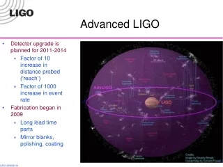
Development Plan • R&D, distributed throughout LSC, well underway • No ‘showstoppers’ found yet! • Integrated Systems Tests of all new aspects of design • Seismic Isolation Test at Stanford ETF, LASTI; Pre-Stabilized Laser (PSL), Input Mode Cleaner, Suspensions at LASTI • High power testing at ACIGA Gingin facility • Configurations, Servo Control Electronics Testing at the GEO Glasgow 10m lab, and in the LIGO 40m Lab • Major Research Equipment (MREFC) funding proposal, Fall ‘02 • Could be in force by early ‘05 • Fabrication, installation, commissioning of installable hardware • May upgrade one observatory, then second system upon proof of success; or all at once – depending upon observations, network at that time, and technical readiness Advanced LIGO
Schedule: Installation • A variety of options, driven by availability of major funding, any observations in the interim, status of other observatories, technical progress • Start with all systems tested, fabricated – commissioning might go faster than anticipated • Upper (Feb ’11) and lower (Nov ’07) bounds on when observing Advanced LIGO
Advanced LIGO • A significant step forward • Exciting astrophysical sensitivity • Challenging but not unrealistic technical goals • Advances the art in materials, mechanics, optics, lasers, servocontrols • A tight and rich collaboration • NSF-funded research • International contributors • Program planned to mesh with fabrication of interferometer components leading to installation of new detectors starting in 2006 or 2007 • Lessons learned from initial LIGO • Thorough testing at LSC facilities to minimize impact on LIGO observation • Coordination with other networked detectors to ensure continuous global observation Advanced LIGO