Advanced LIGO
Advanced LIGO. David Shoemaker NSF LIGO Review 23 October 2002. Advanced LIGO. LIGO mission: detect gravitational waves and initiate GW astronomy Next detector Must be of significance for astrophysics

Advanced LIGO
E N D
Presentation Transcript
Advanced LIGO David Shoemaker NSF LIGO Review 23 October 2002 LIGO Laboratory
Advanced LIGO • LIGO mission: detect gravitational waves and initiate GW astronomy • Next detector • Must be of significance for astrophysics • Should be at the limits of reasonable extrapolations of detector physics and technologies • Should lead to a realizable, practical, reliable instrument • Should come into existence neither too early nor too late • Advanced LIGO: 2.5 hours = 1 year of Initial LIGO • Volume of sources grows with cube of sensitivity • ~15x in sensitivity; ~ 3000 in rate LIGO Laboratory
Anatomy of the projected Adv LIGO detector performance • Suspension thermal noise • Internal thermal noise • Newtonian background,estimate for LIGO sites • Seismic ‘cutoff’ at 10 Hz • Unified quantum noise dominates at most frequencies for fullpower, broadband tuning • NS Binaries: for two LIGO observatories, • Initial LIGO: ~20 Mpc • Adv LIGO: ~300 Mpc • Stochastic background: • Initial LIGO: ~3e-6 • Adv LIGO ~3e-9 Initial LIGO 10-22 10-23 10-24 10-25 1 kHz 100 Hz 10 Hz LIGO Laboratory
Design overview 40 KG SAPPHIRETEST MASSES ACTIVE ISOLATION QUAD SILICASUSPENSION 200 W LASER,MODULATION SYSTEM LIGO Laboratory
Interferometer subsystems LIGO Laboratory
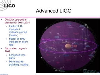
Baseline Plan • Initial LIGO Observation 2002 – 2006 • 1+ year observation within LIGO Observatory • Significant networked observation with GEO, LIGO, TAMA • Structured R&D program to develop technologies • Conceptual design developed by LSC in 1998 • Cooperative Agreement carries R&D to Final Design, 2005 • Proposal Fall 2002 for fabrication, installation • Long-lead purchases planned for 2004 • Sapphire Test Mass material, seismic isolation fabrication • Prepare a ‘stock’ of equipment for minimum downtime, rapid installation • Start installation in 2007 • Baseline is a staged installation, Livingston and then Hanford • Start coincident observations in 2009 LIGO Laboratory
Adv LIGO: Top-level Organization • Scientific impetus, expertise, and development throughout the LIGO Scientific Collaboration (LSC) • Remarkable synergy • LIGO Lab staff are quite active members! • Strong collaboration GEO-LIGO at all levels • Genesis and refinement of concept • Teamwork on multi-institution subsystem development • GEO taking scientific responsibility for two subsystems (Test Mass Suspensions, Pre-Stabilized Laser) • UK and Germany planning substantial material participation • LIGO Lab • Responsibility for Observatories • Establishment of Plan – for scientific observation, for development • Main locus of engineering and research infrastructure …now, where are we technically in our R&D program? LIGO Laboratory
Laser 40 KG SAPPHIRETEST MASSES ACTIVE ISOLATION QUAD SILICASUSPENSION LIGO Laboratory
Pre-stabilized Laser • Require optimal power, given fundamental and practical constraints: • Shot noise: having more stored photons improves sensitivity, but: • Radiation pressure: dominates at low frequencies • Thermal focussing in substrates: limits usable power • Optimum depends on test mass material, 80 – 180 W • Initial LIGO: 10 W • Challenge is in the high-power ‘head’ (remaining design familiar) • Coordinated by Univ. of Hannover/LZH, will lead subsystem • Three groups pursuing alternate design approaches to a 100W demonstration • Master Oscillator Power Amplifier (MOPA) [Stanford] • Stable-unstable slab oscillator [Adelaide] • Rod systems [Hannover] • All have reached ‘about’ 100 W, final configuration and characterized are the next steps • Concept down-select December 2002 • Proceeding with stabilization, subsystem design LIGO Laboratory
Input Optics, Modulation 40 KG SAPPHIRETEST MASSES ACTIVE ISOLATION QUAD SILICASUSPENSION LIGO Laboratory
Input Optics • Subsystem interfaces laser light to main interferometer • Modulation sidebands applied for sensing system • Beam cleaned and stabilized by transmission though cavity • Precision mode matching from ~0.5 cm to ~10 cm beam • Challenges in handling high power • isolators, modulators • Mirror mass and intensity stabilization (technical radiation pressure) • University of Florida takes lead • Design is based on initial LIGO system • Design Requirements Review held in May 2001: very successful • Many incremental innovations due to • Initial design flaws (mostly unforeseeable) • Changes in requirements LIGO 1 LIGO II • Just Plain Good Ideas! • New Faraday isolator materials: 45 dB, 150 W • Larger masses (radiation pressure), vacuum tubes (layout) • Thermal mode matching • Preliminary design underway LIGO Laboratory
Test Masses 40 KG SAPPHIRETEST MASSES ACTIVE ISOLATION QUAD SILICASUSPENSION 200 W LASER,MODULATION SYSTEM LIGO Laboratory
Sapphire Core Optics • Focus is on developing data needed for choice between Sapphire and Fused Silica as substrate materials • Sapphire promises better performance, lower cost; feasibility is question • Progress in fabrication of Sapphire: • 4 full-size Advanced LIGO boules, 31.4 x 13 cm, grown • Delivery in November 2002 – destined for LASTI Full Scale Test optics • Homogeneity compensation by polishing: RMS 60 nm 15 nm • Progress needed in mechanical loss measurements, optical absorption • Downselect Sapphire/Silica in May 2003 LIGO Laboratory
Mirror coatings 40 KG SAPPHIRETEST MASSES ACTIVE ISOLATION COATINGS QUAD SILICASUSPENSION 200 W LASER,MODULATION SYSTEM LIGO Laboratory
Coatings • Evidently, optical performance is critical – • ~1 megawatt of incident power • Very low loss in scatter, absorption required –and obtained • Thermal noise due to coating mechanical loss also significant • Source of loss is associated withTa2O5, not SiO2 • May be actual material loss, or stress induced • Looking for alternatives • Niobia coatings optically ok, mechanical losses slightly better • Alumina, doped Tantalum, annealing are avenues being pursued • Need ~10x reduction in lossy material to have coating make a negligible contribution to noise budget – not obvious Standardcoating LIGO Laboratory
Thermal Compensation 40 KG SAPPHIRETEST MASSES ACTIVE ISOLATION COATINGS QUAD SILICASUSPENSION 200 W LASER,MODULATION SYSTEM LIGO Laboratory
Active Thermal Compensation • Removes excess ‘focus’ due to absorption in coating, substrate • Two approaches possible, alone or together: • quasi-static ring-shaped additional heat (probably on compensation plate, not test mass itself) • Scan (raster or other) to complement irregular absorption • Models and tabletop experiments agree, show feasibility • Indicate that ‘trade’ against increased sapphire absorption is possible • Next: development of prototype for testing on cavity in ACIGA Gingin facility LIGO Laboratory
Seismic Isolation 40 KG SAPPHIRETEST MASSES ACTIVE ISOLATION COATINGS QUAD SILICASUSPENSION 200 W LASER,MODULATION SYSTEM LIGO Laboratory
Isolation: Requirements • Requirement: render seismic noise a negligible limitation to GW searches • Newtonian background will dominate for >10 Hz • Other ‘irreducible’ noise sources limit sensitivity to uninteresting level for frequencies less than ~20 Hz • Suspension and isolation contribute to attenuation • Requirement: reduce or eliminate actuation on test masses • Actuation source of direct noise, also increases thermal noise • Seismic isolation system can reduce RMS/velocity through inertial sensing, and feedback • Acquisition challenge greatly reduced • Choose to require RMS of <10^-11 m Seismiccontribution Newtonianbackground LIGO Laboratory
Isolation I: Pre-Isolator • Need to attenuate excess noise in 1-3 Hz band at LLO • Using element of Adv LIGO • Aggressive development of hardware, controls models • Prototypes in test • Dominating Seismic Isolationteam effort, until early 2003 LIGO Laboratory
Isolation II: Two-stage platform • Stanford Engineering Test Facility Prototype • Mechanical system complete • Instrumentation being installed for modal characterization • The original 2-stage platform continues to serve as testbed in interim • Recent demonstration of sensor correction and feedback over broad low-frequencyband LIGO Laboratory
Suspension 40 KG SAPPHIRETEST MASSES ACTIVE ISOLATION COATINGS QUAD SILICASUSPENSION 200 W LASER,MODULATION SYSTEM LIGO Laboratory
Suspensions • Design based on GEO600 system, using silica suspension fibers for low thermal noise, multiple pendulum stages for seismic isolation • PPARC proposal: significant financial and technical contribution; quad suspensions, electronics, and some sapphire substrates • U Glasgow, Birmingham, Rutherford Appleton • Success of GEO600 a significant milestone • A mode cleaner triple suspension prototype now being built for LASTI Full Scale Test • Both fused silica ribbon and dumbbell fiber prototypes are now being made and tested • Challenge: developing means to damp solidbody modes quietly • Eddy current damping has been tested favorably on a triple suspension • Interferometric local sensor another option LIGO Laboratory
GW Readout 40 KG SAPPHIRETEST MASSES ACTIVE ISOLATION COATINGS QUAD SILICASUSPENSION 200 W LASER,MODULATION SYSTEM LIGO Laboratory
GW readout, Systems • Responsible for the GW sensing and overall control systems • Addition of signal recycling mirror increases complexity • Permits ‘tuning’ of response to optimize for noise and astrophysical source characteristics • Requires additional sensing and control for length and alignment • Glasgow 10m prototype, Caltech 40m prototype in construction, early testing • Mode cleaner together and in locking tests at 40m • Calculations continue for best strain sensing approach • DC readout (slight fringe offset from minimum) or ‘traditional’ RF readout • Hard question: which one shows better practical performance in a full quantum-mechanical analysis with realistic parameters? • Technical noise propagation also being refined LIGO Laboratory
Advanced LIGO • A great deal of momentum and real progress in every subsystem • Details available in breakout presentations/Q&A • No fundamental surprises as we move forward; concept and realization remain intact with adiabatic changes • When there is ‘competition’ for resources with Initial LIGO commissioning, Initial LIGO always wins, as it should • Study of costs in progress • Rough figure: $100M, for 3 full interferometers, materials and manpower, assuming no cost sharing with international partners • Schedule for operation in 2009 requires good progress on • Technical front: return to Adv LIGO focus for Seismic team • Funding front: submission this year, possible early funding for long-lead items LIGO Laboratory