Download
1 / 22
260 likes | 701 Vues
RF Power Amplifiers for Wireless Communications. Steve C. Cripps 이창현. 2.5 Loadline Theory. Ideal Loadline match. 2.5 Loadline Theory. R L 값의 변동 V=IR. 2.5 Loadline Theory. Reactance, Susceptance. .6 Package Effects and Refinements to Load-Pull Theory.

E N D
RF Power Amplifiers for Wireless Communications Steve C. Cripps 이창현
2.5 Loadline Theory • Ideal Loadline match
2.5 Loadline Theory • RL값의 변동 • V=IR
2.5 Loadline Theory • Reactance, Susceptance
.6 Package Effects and Refinements to Load-Pull Theory • Load-Pull theory needs a simple extension • Comparisons with measured data
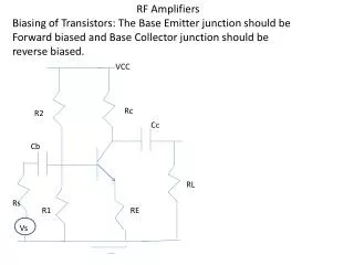
.8 ClassA Design Example • Define target specs, select device • 제조사에서 제공한 data ㅡ> Loadline match • Set up schematic and output matching topology to give ROPT at plane “A” • Parasitic components에 주의 • Design input match using linear (s-parameter) methods
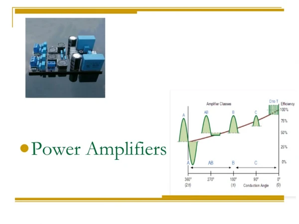
3. Conventional High-Efficiency Amplifier Modes • High-efficiency amplifier modes • “reduced conduction angle” • class AB, B, C • Low quiescent current 로 bias • Harmonics be shorted at the output • PUF(power utilization factor) • Ratio of Rfpower delivered by a device
.1 Reduced Conduction Angle-Waveform Analysis Class C Class B Class AB Class A
.1 Reduced Conduction Angle-Waveform Analysis • Efficiency vs • PUF Imax/π
.3 Reduced Conduction Angle Mode Analysis • 이상적인 소자특성 가정 • 4개의 parameters • Vq : input dc bias point • Vs : amplitude of input signal(Vs = 1 - Vq) • Vk : turn-on transistor character(knee = 0) • RL
.3 Reduced Conduction Angle Mode Analysis • Vq = 0.5 • Vs = 0.5
.3 Reduced Conduction Angle Mode Analysis • Vq = 0.25 • Vs = 0.75
.3 Reduced Conduction Angle Mode Analysis • Vq = 0 • Vs = 1
.3 Reduced Conduction Angle Mode Analysis • Vq = -0.5 • Vs = 1.5 • Breakdown
.4 Effect of Transistor “Knee” • Class B • Vq = 0, Vs = 1 • Vk = 0.2, Vout = 1 • Vq = 0, Vs = 1 • Vk = 0.2, Vout = 0.9