Download
1 / 33
330 likes | 457 Vues
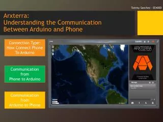
Tommy Sanchez - EE400D. Arxterra : Understanding the Communication Between Arduino and Phone. Connection Type: How Connect Phone To Arduino. Communication from Phone to Arduino. Communication from Arduino to Phone. Connection Type: How to Connect Phone to Arduino.

E N D
Tommy Sanchez - EE400D Arxterra:Understanding theCommunication Between Arduino and Phone Connection Type: How Connect Phone To Arduino Communication fromPhone to Arduino Communication fromArduino to Phone
Connection Type:How to Connect Phone to Arduino There are two ways to connect your phone.Connection Type 1: OTG and Connection Type 2: ADB Connection Type 1: OTG This method allows USB devices (such as a phone) to act as a host. In this method you use a USB to OTG adapter. This method works on both Arduino Uno or Mega ADK. The type BUSB input is used.
Connection Type:How to Connect Phone to Arduino Connection Type 2: ADB (Android Debug Bridge)In our implementation it’s called Microbridge. This method allows communication from the type A input of an Arduino Mega ADK. In other words no adapter is required here.
Connection Type:Which Method Should You Choose Connection Type 1: OTG Any phone compatible with the Arxterra App can connect using this method. Connection Type 2: ADBFor this method your phone must be compatible with the Arxterra App and you must also have USB debugging enabled on your phone(See your phone manual). You must also have the ArduinoADB library(link provided on next slide). If your phone does not communicate even with debugging enabled then use Connection Type1.
On The App:Choosing Arduino Connection Protocol Base On Connection Type Depending on whether the OTG or ADB connection type is being used, the Arduino Connection Protocol must be changed accordingly. • If using ADBchoose Microbridge. • If using OTGchoose Android as Host
The Code: There are two other sketch’s available if desired, one specifically for Rosco (OTG) and one for Pathfinder(ADB) that only work for that connection type. https://github.com/arxterra Note: A hybrid code of these two is coveredin this PowerPoint. In order to simplify communication there is one Arduino sketch that accounts for both connection types. It can be found by going to the link shown below along with the necessary libraries: https://drive.google.com/folderview?id=0BzOzV5VEB-CjY05SQ3lkMDR6VHM&usp=sharing The following slides will talk about how the communication works and where to add your code using this Arduino sketch.
Communication:Quick Robot Configuration Robot Configuration In this section at the top of the sketch you configure your connection type, battery types and if using an ultrasonic sensor. Reading the comments here will help you get started with how you should configure each option.
Communication:Quick Robot Configuration Robot Configurationpinouts_robot.h The “pinouts_robot.h” tab is where you assign your specific pin configuration for the predefined identifiers. For example, Clean_BAT_PIN, a pin designated for your clean power, is defined to be pin A3.
Communication:Phone to Arduino Commands Command ID: The Arxterra Control Panel is set up for the following Phone to Arduino Commands These are also all defined in the Arduino Sketch. With the exception of custom commands which are determined by you.
Communication:Phone to Arduino Command ID and Associated Bytes: [byte array index] descripton [0] = 0x01 (MOVE) [1] = left run (FORWARD, BACKWARD, BRAKE, RELEASE) [2] = left speed 0 to 255 [3] = right run (FORWARD, BACKWARD, BRAKE, RELEASE) [4] = right speed 0 to 255
Communication:Phone to Arduino Command ID and Associated Bytes: [byte array index] descripton [0] = 0x02 (CAMERA_MOVE) [1] = pan degrees (Most Significant Byte) 0 for most servos [2] = pan degrees (0 to 180 for most servos) [3] = tilt degrees (Most Significant Byte) 0 for most servos [4] = tilt degress (0 to 180 for most servos)
Communication:Phone to Arduino Command ID [byte array index] descripton [0] = 0x04 (CAMERA_HOME) In these two cases there are no associated bytes Command ID [byte array index] descripton [0] = 0x05 (CAMERA_RESET)
Communication:Phone to Arduino Command ID and Associated Bytes: Read Write [byte array index] descripton [0] = 0x06 (EEPROM_READ) [1] = Address High [2] = Address Low [3] = Number Bytes [byte array index] descripton [0] = 0x07 (EEPROM_WRITE) [1] = Address High [2] = Address Low [3] = Number Bytes [4] = Data (Most Significant Byte) [5] = ... [N] = Data (Least Significant Byte) N
Communication:Phone to Arduino Command ID Command ID [byte array index] descripton [0] = 0x0B (WAKEUP) [byte array index] descripton [0] = 0x08 SAFE_ROVER) Command ID In all cases there are no associated bytes [byte array index] descripton [0] = 0x0A (SLEEP)
Communication:Phone to Arduino Command ID and Associated Bytes: [byte array index] descripton [0] = command ID in range of 0x40 to 0x5F (64 to 95) [1 to ?] = Data as dictated by data type user configured Take a look at the Custom Commands Tutorial for examples: http://arxterra.com/creating-custom-commands-with-the-arxterra-application/
Communication:Phone to ArduinoHow It Receives Commands OTG With OTG type the following is executed to obtain the Command ID and it’s associated bytes. They are put into an array called data[]. The function commandHandler() uses this data array.
Communication:Phone to ArduinoHow It Receives Commands ADB With adb type the following Interrupt is executed to obtain the Command ID and it’s associated bytes. They are put into an array called data[]. The function commandHandler() uses this data array.
Communication:Phone to ArduinocommandHandler() commandHandler() : This function is where you will decide what your robot does based on the command received. cmd is set equal to the Command ID which is in data[0]
Communication:Phone to ArduinocommandHandler() commandHandler() : As an example if your command ID(data[0]) is 0x01, that means you received a Move command. You would then be in the “if (cmd == MOVE)” section. Here would be your code for Movement. The kind of movement can be decided based on the associated bytes(i.e data[1]-data[4]).
Communication:Phone to ArduinocommandHandler() commandHandler() : When using OTG connection. The Communicator app will show the data coming in. All the ones shown to the right are Move instructions with its associated 4 bytes. Only a few have been highlighted for illustrative purposes. You can decide what the associated bytes mean for your application Recall:[byte array index] descripton [0] = 0x01 (MOVE) [1] = left run (FORWARD(1), BACKWARD(2), BRAKE(4), RELEASE) [2] = left speed 0 to 255 [3] = right run (FORWARD(1), BACKWARD(2), BRAKE(4), RELEASE) [4] = right speed 0 to 255
Communication:Phone to ArduinocommandHandler() commandHandler() : When using ADB connection you can view incoming data from the Arduino Serial Monitor. All the ones shown to the right are Move instructions with its associated 4 bytes. This is the same idea as in the previous slide.
Communication:Phone to ArduinocommandHandler() commandHandler() : On the Arxterra app with the debug switch to enable you should also be able to see what kind of data you are receiving on the window space with either connection type(OTG or ADB).
Communication:Phone to ArduinocommandHandler() Byte array index [0] [1] [2] [3] [4] Move forward Slowly commandHandler() : In order to help you better understand how you can translate the associated bytes using the convention at the bottom right, the byte arrays highlighted are illustrated in a structured manner. Move forward faster Stop Turn Right Slowly Recall:[byte array index] descripton [0] = 0x01 (MOVE) [1] = left run (FORWARD(1), BACKWARD(2), BRAKE(4), RELEASE) [2] = left speed 0 to 255 [3] = right run (FORWARD(1), BACKWARD(2), BRAKE(4), RELEASE) [4] = right speed 0 to 255
Communication:Phone to ArduinocommandHandler() commandHandler() : Back in our example the MOVE section called a move() function. This function handles what kind of move to do (left, right, forward, backward) based on the data while leaving that section uncluttered. Again, the associated bytes can be used to help you decide direction.
Communication:Phone to ArduinocommandHandler() commandHandler() : You’ll notice that in the commandHandler function, all the Phone to Arduino Commands are checked. On the right is the check for the CAMERA_MOVE command ID. If 0x02 is the command received it calls a move_camera function. (used for pan and tilt) Recall: [byte array index] descripton [0] = 0x02 (CAMERA_MOVE) [1] = pan degrees (Most Significant Byte) 0 for most servos [2] = pan degrees (0 to 180 for most servos) [3] = tilt degrees (Most Significant Byte) 0 for most servos [4] = tilt degress (0 to 180 for most servos)
Communication:Phone to ArduinocommandHandler() commandHandler() :CUSTOM COMMANDS If you have a custom command you will have to add your own elseif check and be aware of What your associated bytes if any are. Naming convention for the command would be up to you. Be sure to look at the PowerPoint on custom commands. Recall: [byte array index] descripton [0] = command ID in range of 0x40 to 0x5F (64 to 95) [1 to ?] = Data as dictated by data type user configured
Communication:Arduino to Phone To send telemetry information from the arduino to phone the following ID’s are used. These are also all defined in the Arduino Sketch. With the exception of custom commands which are determined by you.
Communication:Arduino to Phone Telemetry ID and Associated Bytes: Custom EEPROM [byte array index] descripton [0] = command ID in range of 0x40 to 0x5F (64 to 95) [1 to ?] = Data as dictated by data type user configured [byte array index] descripton [0] = 0x07 (EEPROM_WRITE) [1] = Address High [2] = Address Low [3] = Number Bytes [4] = Data (Most Significant Byte) [5] = ... [N] = Data (Least Significant Byte) N
Communication:Arduino to PhonesendData() Send Data: The sendData function is used to check whether there has been a change in anything from the telemetry table on the previous slides. The two if statements on the right check if a new pan or tilt position was detected and if so go to the sendPacket function with this information.
Communication:Arduino to PhonesendData() Send Data: For the Ultrasonic sensor, telemetry is only sent to the phone if the difference from a previous ping to the new ping is greater than the tolerance. Again if this is true, the information is used by the sendPacket function.
Communication:Arduino to PhonesendData() Send Data: The other telemetry checks in this function work much the same way of detecting a change. If custom commands are used this is where you would add a telemetry check based on your robot needs. The Example on the right could be used as a template.
Communication:Arduino to PhonesendPacket() sendPacket: If any change is detected in sendData that information is taken over to the sendPacket function. This function contains the ID for the telemetry and itsassociated values. Depending on if you’re using OTG or ADB connection type the information is sent to the phone accordingly.
Extra Resources/Information Setting Up the Code For The Arduino ADK: Tutorial Provided by Ryan Fiske (Fall 2013) http://www.arxterra.com/wp-content/uploads/2013/10/ArxterraCodeSetup.pdf USB to USB OTG cable to connect to Android phone using the OTG connection Type Tutorial on logging in to control panel and applicationshttp://www.arxterra.com/get-up-and-running-with-the-arxterra-control-panel-android-applications/ Tutorial on Custom Commands on the Arxterra Control Panel/Apphttp://www.arxterra.com/creating-custom-commands-with-the-arxterra-application/