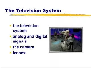
The Television System
The Television System. Television Fundamentals. Television Broadcasting Fundamentals. All TV stations generate and radiate high frequency RF carrier waves. Using modulation , picture & sound information is superimposed on the carriers.

The Television System
E N D
Presentation Transcript
The Television System Television Fundamentals
Television Broadcasting Fundamentals • All TV stations generate and radiate high frequency RF carrier waves. • Using modulation, picture & sound information is superimposed on the carriers. • Sidebands of the carriers are produced, an upper and lower sideband extending above & below carrier frequencies. • These sidebands contain the information which was transmitted from the station to the TV recievers.
Television Broadcasting Fundamentals • A TV station has two transmitters: • An AM transmitter for the picture / video signals and the synchronizing (sync) signals • An FM transmitter for the sound signals • In video signals, it consists of two kinds of video signals: • Luminance – for monochrome / black-and-white signal • Chrominance – for chroma / color signal
Channel and Bandwidth Considerations • Each TV station is assigned a 6-MHz range of frequencies. All video, chroma, sync and sound signals are transmitted within this 6-Mhz bandpass. • Because of this, it utilizes an off-centered video carrier frequency and the unequal upper and lower video sidebands known as vestigial sideband transmission.
Analog TV Standards • NTSC (National Television System Committee technical standard) - used in North America, Japan, South Korea, Burma, Taiwan, the Philippines, and much of South America. • PAL (Phase Altering Line standard) -used in most of Europe, Asia (except USSR), Africa, and Australia, and parts of South America. • SECAM (Sequential Color And Memory standard) - used in the former USSR, France, and parts of Eastern Europe, the Middle East, and Africa.
Television Broadcasting Channels • Low band VHF: • CH 2 – 6 ; (54 – 88 MHz) • High band VHF: • CH 7 – 13 ; (174 – 216 MHz) • UHF Channels: • CH 14 – 83 ; (470 – 890 MHz)
Terrestrial Analog Television Broadcasting • Illustrated below is the spectrum for tv channel 2.
Pixel • Smallest area of light or shade on image • Picture detail • Picture element • pel
Television Basics • Video systems form pictures by scanning • The North American standard is 525 lines • European standard is 625 lines • Scan rates are: • North America = approx. 30 frames per sec • Europe = 25 frames per second
Interlaced Images • Interlaced images allow for easier transmission of moving images at higher resolution. • Half pictures in 1/60th a second..30fps. • Trade offs include some image jitter: • Jagged edges from motion occur because the object is in a different location every 1/60 of a second. The even lines show the object in one position while the odd lines show the image in a different position.
Interlaced Images • Motion artifacts and horizontal "line twitter" are the most notorious NTSC artifacts. • The closer you sit to your video display device and the larger the video display device appears, the easier it will be to see NTSC artifacts in images. • Some newer television sets employ powerful image processing that can make NTSC artifacts very difficult to find. HDTV (high-definition digital television) includes standards for higher-resolution progressive scanning, which eliminates the video image artifacts we have endured for over 50 years. • Unfortunately, many HDTV products have chosen the higher resolution 1080i format (1080 lines interlaced) to use to convert everything regardless of how it was broadcast or recorded. This is unfortunate because interlace artifacts remain quite visible even in the 1080i format.
Television Basics • The number of lines scanned in 1 second is 15 750 lines. • Time for each horizontal scanning line is 63.5 µs. • About 10 µs of this is used by the horizontal synch pulse. • The electron beam that traces the picture is blanked during the time intervals in which the beam retraces its path. • The time intervals where blanking takes place are called the horizontal and verticalblanking intervals
Review • Frame horizontal scanning lines: • 525 lines • Field horizontal scanning lines: • 262 ½ lines • Frame Rate: • 30 Hz • Field Rate: • 60 Hz • Lines scanned in 1 sec: • 15 750 lines • Time for scanning 1 line: • 63.5 µs
IRE (Institute of Radio Engineers) Scale • An arbitrary unit of measurement equal to 1/100 of the excursion from blanking to reference white level. • In NTSC systems, • 100 IRE = 714mV • 140 IRE = 1-volt pp
Standards of the World • NTSC • National Television Standards Committee • PAL • Phase Alternation by Line • SECAM • Sequential Technique and Memory Storage
Color Signals • Luminance (Y ) • Contains brightness variations of the picture information. • Used to reproduce the picture in black and white, or monochrome sets. • Chrominance (C) • Contains the color information. • 3.58 MHz is the frequency for color.
Color Signals • Three signals that make up the color composite signal are: • Y = luminance signal • I = in-phase component of the color signal • Q = quadrature component of the color signal • In-phase and quadrature refer to the process by which the chrominance (color)signal is combined with the luminance signal
Equations for Y,I,Q • Y = 0.30R + 0.59G + 0.11B • I = 0.60R - 0.28G - 0.32B • Q = 0.21R - 0.52G + 0.31B