Download

1 / 79
880 likes | 1.37k Vues
Basic Crystallography Part 2 Theory and Practice of X-ray Crystal Structure Determination. Charles Campana, Ph.D. Senior Applications Scientist Bruker AXS. Course Overview. Basic Crystallography – Part 1 Introduction – Crystals and Crystallography Crystal Lattices and Unit Cells

E N D
Basic CrystallographyPart 2 Theory and Practice of X-ray Crystal Structure Determination Charles Campana, Ph.D. Senior Applications Scientist Bruker AXS
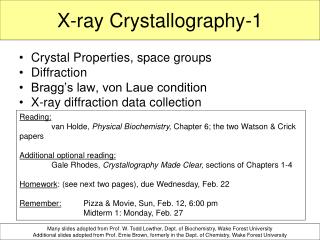
Course Overview Basic Crystallography – Part 1 • Introduction – Crystals and Crystallography • Crystal Lattices and Unit Cells • Generation and Properties of X-rays • Bragg's Law and Reciprocal Space • X-ray Diffraction Patterns Basic Crystallography – Part 2 • Review of Part 1 • Selection and Mounting of Samples • Unit Cell Determination • Intensity Data Collection • Data Reduction • Structure Solution and Refinement • Analysis and Interpretation of Results
Review of Part 1 Important Concepts
Important Concepts - Crystals • A crystal is made up of atoms, molecules, or ions arranged in an orderly repeating pattern extending in all three spatial dimensions. • The crystal is similar to a 3-dimensional ‘wallpaper pattern’ made up of millions of identical small ‘bricks’ or unit cells. The size, shape and dimensions of the unit cell are called lattice parameters(a, b, c, alpha, beta, and gamma). • The lattice parameters are chosen according to accepted conventions for the 7 crystal systems (triclinic, monoclinic, orthorhombic, trigonal, tetragonal, hexagonal and cubic). • Crystal lattices are also classified into 14 Bravais lattices, which include primitive (P), end-centered (A, B, or C), body-centered (I), and face-centered (F) lattices. • When all possible three-dimensional rotational and translational symmetry elements are combined, they form a set of 230 crystallographic space groups.
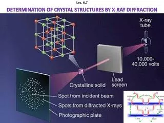
Important Concepts – X-rays • X-rays are produced by accelerating high-energy electrons toward a metal target (anode). Collision of the electrons with the anode generates Bremsstrahlung (white) radiation as well as characteristic Ka and Kb radiation. The useful range of X-ray wavelengths for XRD applications: 0.05 nm to 0.25 nm or 0.5 Å to 2.5 Å (1 nm = 10-9 meters = 10 Å). • When monochromatic X-rays interact with the electrons of the atoms, they undergo coherent scattering. When the atoms are arranged in a regular array, they produce a diffraction pattern due to constructive and destructive interference of electromagnetic waves. The properties of the diffraction pattern are well described by Bragg’s Law.
Important Concepts – Diffraction Patterns and Reciprocal Space • When X-rays are diffracted from a parallel set of planes with Miller indices h, k, and l, they produce a reflection with the corresponding h, k, and l indices. • The immediate result of the X-ray diffraction experiment is a list of X-ray reflections hkl and their intensities I. • We can arrange the reflections on a 3D-grid based on their h, k and lvalues. The smallest repeat unit of this reciprocal lattice is known as the reciprocal unit cell; the lengths of the edges of this cell are inversely related to the dimensions of the real-space unit cell. • This concept is known as reciprocal space; it emphasizes the inverse relationship between the diffracted intensities and real space.
Important Concepts – Fourier Transform Relationships Real Space • Unit Cell (a, b, c, , , ) • Electron Density, (x, y, z) • Atomic Coordinates –x, y, z • Thermal Parameters – Bij • Bond Lengths (A) • Bond Angles (º) • Crystal Faces Reciprocal Space • Diffraction Pattern • Reflections • Integrated Intensities – I(h,k,l) • Structure Factors – F(h,k,l) • Phase – (h,k,l)
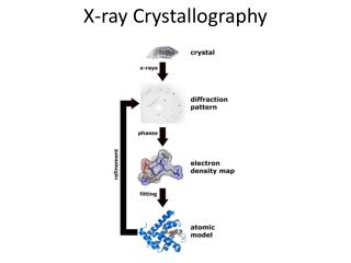
Flowchart for X-ray Structure Determination Select, mount, and optically align a suitable crystal Evaluate crystal quality; obtain unit cell geometryand preliminary symmetry information Measure intensity data Data reduction Solve the structure Complete and refine the structure Adapted from William Clegg “Crystal Structure Determination” Oxford 1998. Interpret the results
X-ray Crystal Structure Determination Selection and Mounting of Sample
Sample Requirements • Prepare and purify material to be analyzed • Grow “X-ray quality” crystals • Slow evaporation • Solvent or vapor diffusion • Sublimation • Select specimen for analysis • Suitable size – 0.10 to 0.50 mm in all dimensions • No obvious cracks or ‘twinning’ • Natural faces, if possible • Use polarizing microscope to screen specimens
Mounting of Samples • Use micro-tools or acupuncture needles and oil to separate selected sample • Mount specimen for analysis • Glass capillary - very air-sensitive samples • Glass fiber (glue) – room temperature • Cryo-Loop (Paratone-N oil) – low temperature • MiTeGen mounts (Paratone-N oil) – low temperature
Goniometer Head Huber model 1004 goniometer head
X-ray Crystal Structure Determination Hardware and Instrumentation
3-Circle Goniometer • The most common type of goniometer is the “3-circle goniometer", which offers two angles of rotation: the ω angle, which rotates about an axis perpendicular to the beam and the φ angle about the loop/capillary axis.The c angle is fixed at the “magic angle” of 54.74° with respect to the ω axis. • The oscillations carried out during data collection involve either the ω axis or the φ axis.
Model of a Kappa Goniometer X-ray crystallography. (2010, April 19). In Wikipedia, The Free Encyclopedia. Retrieved 16:17, April 21, 2010, from http://en.wikipedia.org/w/index.php?title=Xray_crystallography&oldid=357005816 Kappa_goniometer_animation.ogg Kappa_goniometer_animation.ogg Kappa_goniometer_animation.ogg
X-ray Sources • The experiment involves irradiating the mounted crystal with a beam of monochromatic X-rays. The standard X-ray source for conventional laboratory systems is a ceramic X-ray tube which operates at 1500 to 2000 W. For very small specimens, micro-focus sources or rotating anode sources may be required. • In all of these systems, the sources produce both Bremsstrahlung (white) radiation and strong characteristic Kα and Kβ lines corresponding to the energy differences between inner-shell electrons of the target metal.
X-ray Tube Radiation Choices The most commonly-used X-ray targets for single crystal X-ray diffraction are copper and molybdenum.
X-ray Sources • The X-rays are usually passed through monochromators or X-ray mirrors to eliminate white radiation and Kβradiation and to produce a single wavelength (Kαradiation only). • This monochromatic beam is then collimated to a single, intense small beam before it is allowed to strike the crystal. • Collimation is done either with a collimator or with monocapillary optics. Pinholes may also be used to adjust the size and shape of the X-ray beam striking the specimen.
Other Modern Laboratory X-ray Sources ImS TXS Rotating Anode
Measurement of Intensity Data The intensities of these reflections may be recorded with a charge-coupled device (CCD) detector.
X-ray Crystal Structure Determination Small Molecule Example
Unit Cell Determination • The experiment generally begins with the measurement of three small sets of images (typically 12 to 30 images per set) with the sample oriented in approximately orthogonal positions. • The positions of the spots (reflections) are then indexed using an auto-indexing routine, which assigns a set of three unique Miller indices (h, k, l) to each of the measured reflections. At the same time, this routine determines the dimensions (a, b, c, a, b ,g and V) of the crystallographic unit cell and calculates an orientation matrix from which the positions of all remaining reflections may be predicted. • A by-product of indexing is determination of the unit cell symmetry, the crystal system and the Bravais lattice.
Density, Volume and Z Value • The density of a crystal is given by: = 1024ZM / NaV where = density in mg·m-3,Z = number of molecules in one unit cell, M = molecular weight in Da, Na = Avogadro’s number = 6.0226×10²³ and V = volume of the unit cell in Å3. • The Z value (number of molecules per unit cell) may be estimated by dividing the unit cell volume by 18 to obtain the number of non-hydrogen atoms in the unit cell (Rule of 18 –where we assume that the volume of a non-hydrogen atom is about 18 Å3, hydrogen atoms are ignored). The result is then divided by the number of non-hydrogen atoms in each molecule to estimate Z (to the nearest whole number).
Small Molecule Example – YLIDAutomatic Unit Cell Determination • Measured 3 sets of 12 images (10 sec. exposure times) • Located 84 reflections above 20s(I) • Indexed 82 of 84 reflections • Determined the unit cell to be orthorhombic P (primitive); note that all angles are 90° • Volume is 994Å3; from this we can calculate that there are ~994/18 = 55.222 non-hydrogen atoms in the unit cell. C11H10O2S has 14 non-hydrogen atoms; 55.22/14 = 3.944 ≈ 4.0 = Z
Small Molecule Example – YLIDIndexed Reflections • These two slides show that all 82 indexes reflections lie at the center of the grid lines 0n all three projections. • These 3 projections also illustrate the concept of reciprocal space. • 0kl projection (k vertical, l horizontal) • h0l projection (l vertical, h horizontal) • hk0 projection (h vertical, k horizontal) 0kl projection
Small Molecule Example – YLIDIndexed Reflections h0l projection hk0 projection
X-ray Crystal Structure Determination Data Collection
Measurement of Intensity Data • One image of spots is insufficient to reconstruct the whole crystal; it represents only a small slice of the full Fourier transform. • To collect the complete diffraction pattern, the crystal must be rotated, in small φ or ω steps, through many combinations of angles, with an image recorded at every step. • However, if the crystal has a higher symmetry, a smaller unique data set be sufficient to solve the structure.
Data Collection Options • Modern instruments offer many options for selecting an optimum data collection strategy for each sample: • Choice of wavelength – Mo or Cu • Crystal-to-detector distance (typically 4.0 to 6.0 cm.) • Scan widths (0.3 to 1.0 degrees per step in w or f) • Exposure time per image (5 to 60 sec.) • Resolution (0.84 Å max. for Cu, 0.77 Å typical for Mo) • Whole “sphere” or minimum unique dataset • Total data collection time • Sample temperature (e.g., RT or 100 K) • Data collection strategies may depend upon: • Size and diffracting power of specimen • Mosaicity and rocking curve • Data collection time available • Stability of compound • Length of maximum unit cell axis
Small Molecule Example – YLIDTypical Data Collection • Goniometer: 3–circle (c fixed at 54.74°) • Radiation choice: Mo ( = 0.71073 Å) • Crystal-to-detector distance: 6.0 cm (60 mm) • Scan width: 0.5° in w • Exposure time: 10 sec. per image • Resolution: 0.77Å (55.00° in 2θ) • Whole “sphere”: 4 runs of 366 images each (512 × 512 mode) • Total data collection time: ~6 hours • Sample temperature: 23° C (296 K)
X-ray Crystal Structure Determination Data Reduction
Data Reduction • The recorded series of two-dimensional diffraction images must be converted into a three-dimensional array of indexed reflections, each of which has an associated intensity, I, and standard deviation, s(I). This process is called data reduction. • The first part of the data reduction process is called integration. This procedure uses the orientation matrix and applies many corrections as it converts the hundreds or thousands of images—containing many thousands of reflections—into a single file, consisting of individual records of the Miller indices, intensity with standard deviation, and direction cosines for each reflection. • The second part of the data reduction uses the direction cosines to correct for absorption of X-rays by the sample, normalizes the sigma values, scales and sorts the data for structure determination, and performs a complete error analysis of the data.
Small Molecule Example – YLIDFinal Unit Cell Parameters • The final unit-cell constants are calculated from the centroids of many thousands of reflections selected from the entire data set and typically have relative errors of less than 3/100,000.
Small Molecule Example – YLIDAbsorption Correction and Scaling
Small Molecule Example – YLIDAbsorption Correction and Scaling
Small Molecule Example – YLIDAbsorption Correction and Scaling
X-ray Crystal Structure Determination Solution of Structures
Symmetry and Space Groups • In crystallography, the space group of a crystal is a description of the symmetry of the crystal, and can have one of 230 types. • The space groups in three dimensions are made from combinations of the 32 crystallographic point groups with the 14 Bravais lattices which belong to one of 7 lattice systems. This results in a space group being some combination of the translational symmetry of a unit cell including lattice centering, the point group symmetry operations of reflection, rotation and improper rotation (also called roto-inversion), and the screw axis and glide plane symmetry operations. The combination of all these symmetry operations results in a total of 230 unique space groups describing all possible crystal symmetries.
Space Group Determination and Formula • The first step in the solution of a crystal structure is the assignment of the space group. In practice, the space group determination is often done automatically, following the data reduction step. • The choice of the space group includes the following considerations: • The crystal system and Bravais lattice • Analysis of “systematically absent” classes of reflections • The evaluation of |E2 -1| values • Relative frequency of occurrence in CSD • The normalized structure factors depend upon having an approximately correct chemical formula. The ‘rule of 18’ should be used to calculate the Z value.
Small Molecule Example – YLIDSpace Group Determination • 5780 reflections read from .hkl file • Bravais lattice is Primitive
Small Molecule Example – YLIDSpace Group Determination • Orthorhombic Primitive Unit Cell Confirmed
Small Molecule Example – YLIDSpace Group Determination Space Group is determined to be P212121 (No. 19)
Small Molecule Example – YLIDSpace Group Determination hk0 layer 0kl layer