Chapter 7. Small-signal admittance
90 likes | 327 Vues
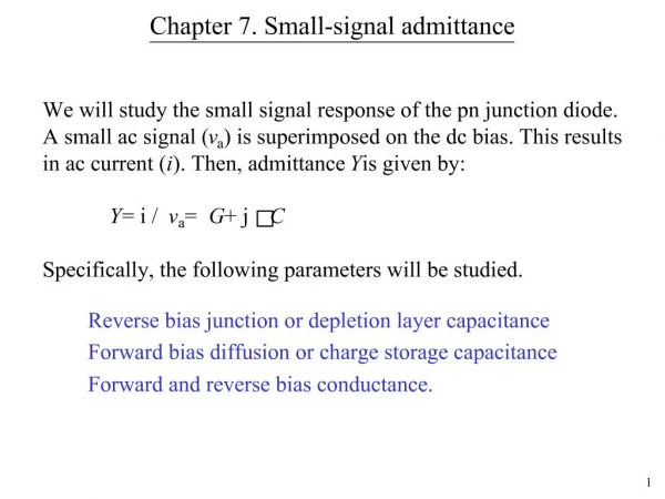
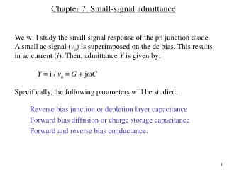
Chapter 7. Small-signal admittance. We will study the small signal response of the pn junction diode. A small ac signal ( v a ) is superimposed on the dc bias. This results in ac current ( i ). Then, admittance Y is given by: Y = i / v a = G + j C

Chapter 7. Small-signal admittance
E N D
Presentation Transcript
Chapter 7. Small-signal admittance We will study the small signal response of the pn junction diode. A small ac signal (va) is superimposed on the dc bias. This results in ac current (i). Then, admittance Y is given by: Y = i / va = G + jC Specifically, the following parameters will be studied. • Reverse bias junction or depletion layer capacitance • Forward bias diffusion or charge storage capacitance • Forward and reverse bias conductance.
Capacitance measurements I = dc i = ac Y = admittance i and va depends on the applied dc bias Model for a diode under ac
Reverse bias junction capacitance pn junction under reverse bias behaves like a capacitor. Such capacitors are used in ICs as voltage-controlled capacitors. Depletion layer width under small ac superimposed on DC bias voltage. Looks similar to a parallel plate capacitor. where W is the depletion layer width under dc bias.
Reverse bias junction capacitance For pn junction For p+n or pn+ junction where NB is the doping on the lightly doped side For asymmetrically doped junction CJ increases with NB1/2 CJ decreases with applied reverse bias
Parameter extraction/profiling C-V data from a pn junction is routinely used to determine the doping profile on the lightly doped side of the junction. 2 1/Cj2 [F–2 ] 1 If the doping on the lightly doped side is uniform, a plot of 1/CJ2 versus VA should be a straight line with a slope inversely proportional to NB and an extrapolated 1/CJ2 = 0 intercept equal to Vbi. 0 –10 –5 0 VA [Volts] Intercept = Vbi
Forward bias diffusion capacitance, CD CD isalso called the charge storage capacitance. Minority carrier charge fluctuation results in diffusion capacitance. Both CJ and CD are always present, but for forward biased case, CD becomes dominant. n p origin of diffusion capacitance. pn0 np0 x For a p+n junction, I = Qp/p where Qp is total excess charge in n-side
CJ Rs CD GD Forward bias conductance Assumes Complicated at higher frequencies. VApplied = VA Equivalent circuit for a diode VJ
Example Consider a p+n junction forward biased such that the forward current is 1 mA. Assume the lifetime of holes is 10–7 s. Calculate the diffusion capacitance and the diffusion resistance. (Review question) The current through the depletion layer will mostly be carried by (holes, electrons: choose one). Plot the current carried by the holes and electrons through the n-type region, assuming that the diffusion length of holes is 1 m. Answer: CD = 3.86 nF rd = 1/GD = 25.9 Ohms