Download
1 / 34
340 likes | 494 Vues
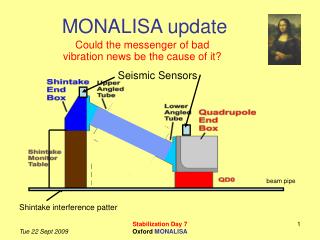
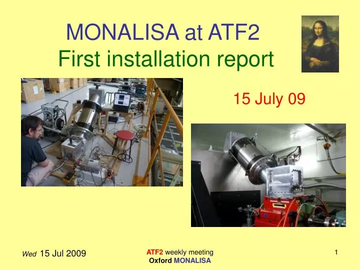
MONALISA at ATF2 First installation report. 15 July 09. Overview. Installation progress ATF2 roof: Initial tests with wooden frame Initial test results ATF2 FF: Mounted at IP in Final Focus Vacuum test Force tests Tilt tests Magnet lateral movement tests. Good progress.

E N D
MONALISA at ATF2First installation report 15 July 09 ATF2 weekly meeting Oxford MONALISA
Overview • Installation progress • ATF2 roof: Initial tests with wooden frame • Initial test results • ATF2 FF: Mounted at IP in Final Focus • Vacuum test • Force tests • Tilt tests • Magnet lateral movement tests ATF2 weekly meeting Oxford MONALISA
Good progress • We kept within our proposed schedule • As set out in ATF2 meeting 17 Jun 09 • All items arrived at KEK 1st July 2009 • Brought to ATF2 roof within 15 mins of arrival • On ATF2 roof • System assembled and retested • Brought to ATF2 Final focus tunnel • Reassembled at IP Thursday 9th July and tested ATF2 weekly meeting Oxford MONALISA
On the roof of the ATF2 ATF2 weekly meeting Oxford MONALISA
Preliminary tests • Reassembled wooden frame on ATF2 roof • Benoit measured vibrations (see his talk) • Closed the vacuum system • Pumped out to 25 Pa • Limited by small leak (1 Pa/s) • Due to lower angled tube • Will be fixed in future by replacing lower angled tube • Vacuum sufficient for test programme ATF2 weekly meeting Oxford MONALISA
Schematic Layout of Pneumatics • Vacuum in end boxes connected through inner bellows • High pressure only connected to outer bellows chamber ATF2 weekly meeting Oxford MONALISA
Recalibrated force sensors • Retested force sensor • Applying loads using spring balance • Force sensor rather noisy • Produces signals up to +/- 10 mV • Readout with NI USB 6009 ADC (14 bit) • Sampled at 5kSa/s • Used LabVIEW to average 5000 readings together ATF2 weekly meeting Oxford MONALISA
Forces on frame during pumping • Cycled bellow chamber pressures • Inner chamber 100 kPa to 25 Pa to 100 kPa • Outer chamber 100 kPa to 140 kPa to 100kPa • Measured forces • Using recalibrated force sensor • Independently calculated forces • Based on SMC pressure sensors • One for each chamber ATF2 weekly meeting Oxford MONALISA
Sensor readout during pumping ATF2 weekly meeting Oxford MONALISA
Over-pressure regulation • Over-pressure regulator does not behave as we would like Overpressure / kPa No response for over-pressure requests less than (50 mbar) 40 Control Signal /V 0 Vmax 0 ATF2 weekly meeting Oxford MONALISA
Required over-pressure regulation • Would want a straight line relationship even for very low over-pressure Overpressure / kPa 40 Control Signal /V 0 Vmax 0 ATF2 weekly meeting Oxford MONALISA
Into the ATF2 tunnel ATF2 weekly meeting Oxford MONALISA
Tunnel preparation Terunua-san installed pipe across the inside of the ATF2 final focus tunnel roof Equipped with 2 hoists ATF2 weekly meeting Oxford MONALISA
Mounting Shintake components • Plate mounted using M30 hooks • End box mounted using hoist Cables ATF2 weekly meeting Oxford MONALISA
Mounting QD0 end box • Beeswax was placed on QD0 surface • To ensure good vibration coupling to magnet ATF2 weekly meeting Oxford MONALISA
End boxes mutually aligned • Laser light projected along accelerator axis • Shintake end box • (left-right adjustable) • Moved to match QD0 end box ATF2 weekly meeting Oxford MONALISA
The DBS was hoisted into place Full assembly completed well within one day ATF2 weekly meeting Oxford MONALISA
Tilt sensor • Tilt change on Shintake ~5+5 mrad • After MONALISA DBS installed at IP ATF2 weekly meeting Oxford MONALISA
DBS pumped out: with rods in • Reached 28 Pa with a different pump • vacuum integrity was unaltered ATF2 weekly meeting Oxford MONALISA
Forces measured pumping down when mounted at ATF2 IP Regulator cycle ~225 s ATF2 weekly meeting Oxford MONALISA
(x,y,z) Physicists coordinates • In the following we’re using the physicists coordinate frame Y Z X ATF2 weekly meeting Oxford MONALISA
Tracking QD0 motion in Z • Set MONALISA at operational pressure • Pumped out vacuum vessel • Over-pressure in outer bellowed chamber • Set up independent tracking of QD0 • Used FARO to survey QD0 position changes • Keyence laser meter tracked QD0 mounted on SD0 base plate ATF2 weekly meeting Oxford MONALISA
KEYENCE tracking QD0 Z QD0 KEYENCE Readout sensor in mV 10 V = 5 mm 1 mV = 0.5 mm Readout with our ADC/LabVIEW DAQ Supported from SD0 ATF2 weekly meeting Oxford MONALISA
FARO survey instrument Retro FARO ATF2 weekly meeting Oxford MONALISA
Comparison of FARO & KEYENCE ATF2 weekly meeting Oxford MONALISA
FARO compared with KEYENCE ATF2 weekly meeting Oxford MONALISA
FARO tracking X and Z ATF2 weekly meeting Oxford MONALISA
Tracking QD0 motion in Z ATF2 weekly meeting Oxford MONALISA
Tracking QD0 motion in X ATF2 weekly meeting Oxford MONALISA
Left-right QD0 mover tests ATF2 weekly meeting Oxford MONALISA
Left-right QD0 mover tests ATF2 weekly meeting Oxford MONALISA
Left-right QD0 mover tests DBS spring constant is small enough to let QD0 move freely ATF2 weekly meeting Oxford MONALISA
What to learn from this measurements? • We are told that static tolerances for QD0: • 100μm in x,y,z • Our measurements show that even with the current pressure control system we meet this tolerance. • The low spring constant of the DBS allows the QD0 mover to move the magnet unhindered. • Dynamic tolerances: vertical: 10 nm, (between Shintake and QD0) horizontal: 500 nm along beam: 10 μm • The question about dynamic motion and impact on the Shintake table will be answered in the next two talks. ATF2 weekly meeting Oxford MONALISA
Summary & Outlook • MONALISA vacuum system worked well • Many thanks for the wonderful support we got! • The next step is to do optics tests with the vacuum system in place to gain calibration constants. • Our goal is to get first position measurements to the Shintake group late next spring. ATF2 weekly meeting Oxford MONALISA