Ray-Tracing: Reflection, Refraction and Shadow
Ray-Tracing: Reflection, Refraction and Shadow. Soon Tee Teoh CS 116B. Reflective Surface. In ray-tracing, we can model a reflective surface rather easily. An example of a reflective surface is a mirror. Law of reflection: Angle of reflection = angle of incidence. Light source. N.

Ray-Tracing: Reflection, Refraction and Shadow
E N D
Presentation Transcript
Ray-Tracing: Reflection, Refraction and Shadow Soon Tee Teoh CS 116B
Reflective Surface • In ray-tracing, we can model a reflective surface rather easily. • An example of a reflective surface is a mirror. • Law of reflection: Angle of reflection = angle of incidence Light source N Reflected ray q Incident ray q surface Angie of incidence Angle of reflection
Reflection Example A reflective sphere reflects its surroundings
Reflection in Ray-Tracing • When the ray from the camera hits a reflective surface, reflect the ray off the reflective surface. Whatever this reflected ray “sees” is the color shown on the pixel. • How to do reflection: • Let the unit vector from the surface to the camera be V. • Let the unit normal of the surface be N. • Then, the reflected vector R = -V + 2N(V.N) Camera N q q V R surface
Combining Reflective and Non-Reflective Components • You can model an object to have reflective and non-reflective components. • For the reflective component, reflect the ray and find the color “seen” by the reflected ray. • For the non-reflective component, use the usual lighting model (ambient + diffuse + specular). • A reflective factor f (0.0 < f < 1.0) is pre-defined. • The final color of the pixel should be fCR + (1-f)CNR • Define f to be a larger value for a more reflective surface.
Multiple Reflections • If the reflected ray hits another reflective object, the reflected ray has to be reflected again. • Then, just proceed as usual. • To prevent infinite number of reflections, people usually set a maximum number of reflections allowed (say 6), and if the ray has been reflected more than this number of times, some arbitrary color (say gray) is returned. reflective non-reflective reflective screen
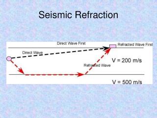
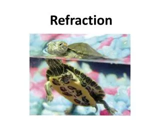
Refraction • Smooth dielectric: A dielectric is a transparent material that refracts light, e.g. diamonds, glass, water. • When light passes from one medium into another, it refracts (or bends). • How does the light bend? It depends on the refractive indices of the two media. • Suppose that the refractive index of the medium (Medium 1) containing the incoming ray is n1, and the refractive index of the other medium (Medium 2) is n2, then, according to Snell’s Law: n1 sin q1 = n2 sin q2 Light source N Incident ray q1 Medium 1 surface Medium 2 Refracted ray q2
Calculating the Refracted Ray • Suppose that the normal of the surface is N. • Suppose that the incident ray (vector from light to the surface) is L. • Suppose that the refracted ray (vector in medium 2) is R. • Suppose, as before, that the refractive index of Medium 1 is n1 and the refractive index of Medium 2 is n2. • Suppose, as before, that the incident angle is q1. • Then, R is calculated according to the following formula: n12 (1 – (L.N)2q1) n1(L – N (L.N)) R = - N 1 - n2 n22 Light source N q1 Incident ray L Medium 1 surface Medium 2 Refracted ray R
Putting It All Together • When light from the air hits a material, part of it can be reflected, part of it can be refracted. • When the ray from the eye hits a dielectric, we can split the ray into a reflective component, and a refractive component, and also add the “intrinsic” color of the material (perhaps by the usual ambient-diffuse-specular lighting model). • So, Colorfinal = kintrinsicColorintrinsic + kreflectionColorreflection + krefractionColorrefraction where kintrinsic + kreflection + krefraction = 1.0 Light source N Incident ray Reflected ray Dielectric surface Refracted ray
Shadow • It is rather straight-forward to make shadows in ray-tracing. • When we’ve calculate the position of the surface to show for a pixel, while calculating lighting for each light source, find out if anything occludes the point. • How to find occlusion? • Just use the same ray-tracing algorithm to look for ray-object intersections. X(t) = P + tD • Here, set P to be the position of the surface point. • Set D to be L – P, where L is the position of the light source. • Normalize D. • Then, an object casts a shadow on P if it intersects the ray, and 0.0 < t < tLight, where tLight is the distance from the surface point to the light source. • Be careful not to consider the point P itself. So, can instead use 0.0001 < t < tLight