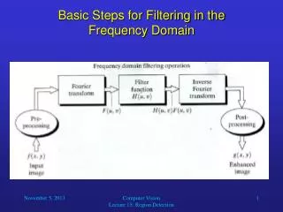
Filtering in the Frequency Domain (Application)
620 likes | 1.14k Vues
Digital Image Processing. Filtering in the Frequency Domain (Application). Christophoros Nikou cnikou@cs.uoi.gr. DFT & Images. Images taken from Gonzalez & Woods, Digital Image Processing (2002).

Filtering in the Frequency Domain (Application)
E N D
Presentation Transcript
Digital Image Processing Filtering in the Frequency Domain(Application) ChristophorosNikou cnikou@cs.uoi.gr
DFT & Images Images taken from Gonzalez & Woods, Digital Image Processing (2002) The DFT of a two dimensional image can be visualised by showing the spectrum of the image component frequencies DFT
DFT & Images Images taken from Gonzalez & Woods, Digital Image Processing (2002)
DFT & Images Images taken from Gonzalez & Woods, Digital Image Processing (2002)
DFT & Images (cont…) Images taken from Gonzalez & Woods, Digital Image Processing (2002) DFT Scanning electron microscope image of an integrated circuit magnified ~2500 times Fourier spectrum of the image
DFT & Images (cont…) Images taken from Gonzalez & Woods, Digital Image Processing (2002)
DFT & Images (cont…) Images taken from Gonzalez & Woods, Digital Image Processing (2002)
Periodicity of the DFT • The range of frequencies of the signal is between • [-M/2, M/2]. • The DFT covers two back-to-back half periods of the signal as it covers [0, M-1].
Periodicity of the DFT (cont...) • For display and computation purposes it is convenient to shift the DFT and have a complete period in [0, M-1]. • From DFT properties: Letting N0=M/2: And F(0) is now located at M/2.
Periodicity of the DFT (cont...) • In two dimensions: and F(0,0) is now located at (M/2, N/2).
DFT & Images (cont…) Images taken from Gonzalez & Woods, Digital Image Processing (2002)
DFT & Images (cont…) Images taken from Gonzalez & Woods, Digital Image Processing (2002)
DFT & Images (cont…) Images taken from Gonzalez & Woods, Digital Image Processing (2002) Although the images differ by a simple geometric transformation no intuitive information may be extracted from their phases regarding their relation.
DFT & Images (cont…) Images taken from Gonzalez & Woods, Digital Image Processing (2002)
The DFT and Image Processing Images taken from Gonzalez & Woods, Digital Image Processing (2002) To filter an image in the frequency domain: • Compute F(u,v) the DFT of the image • Multiply F(u,v) by a filter function H(u,v) • Compute the inverse DFT of the result
The importance of zero padding Images taken from Gonzalez & Woods, Digital Image Processing (2002)
The importance of zero padding (cont...) Images taken from Gonzalez & Woods, Digital Image Processing (2002)
The importance of zero padding (cont...) Images taken from Gonzalez & Woods, Digital Image Processing (2002)
Some Basic Frequency Domain Filters Images taken from Gonzalez & Woods, Digital Image Processing (2002) Low Pass Filter High Pass Filter
Some Basic Frequency Domain Filters Images taken from Gonzalez & Woods, Digital Image Processing (2002)
Some Basic Frequency Domain Filters Images taken from Gonzalez & Woods, Digital Image Processing (2002)
Smoothing Frequency Domain Filters • Smoothing is achieved in the frequency domain by dropping out the high frequency components • The basic model for filtering is: G(u,v) = H(u,v)F(u,v) • where F(u,v) is the Fourier transform of the image being filtered and H(u,v) is the filter transform function • Low pass filters – only pass the low frequencies, drop the high ones.
Ideal Low Pass Filter Images taken from Gonzalez & Woods, Digital Image Processing (2002) Simply cut off all high frequency components that are a specified distance D0 from the origin of the transform. Changing the distance changes the behaviour of the filter.
Ideal Low Pass Filter (cont…) The transfer function for the ideal low pass filter can be given as: where D(u,v) is given as:
Ideal Low Pass Filter (cont…) Images taken from Gonzalez & Woods, Digital Image Processing (2002) An image, its Fourier spectrum and a series of ideal low pass filters of radius 5, 15, 30, 80 and 230 superimposed on top of it.
Ideal Lowpass Filters (cont...) Images taken from Gonzalez & Woods, Digital Image Processing (2002) • ILPF in the spatial domain is a sinc function that has to be truncated and produces ringing effects. • The main lobe is responsible for blurring and the side lobes are responsible for ringing.
Ideal Low Pass Filter (cont…) Images taken from Gonzalez & Woods, Digital Image Processing (2002) ILPF of radius 5 Originalimage ILPF of radius 15 ILPF of radius 30 ILPF of radius 230 ILPF of radius 80
Butterworth Lowpass Filters Images taken from Gonzalez & Woods, Digital Image Processing (2002) • The transfer function of a Butterworth lowpass filter of order nwith cutoff frequency at distance D0 from the origin is defined as:
Butterworth Lowpass Filters (cont...) Images taken from Gonzalez & Woods, Digital Image Processing (2002)
Butterworth Lowpass Filter (cont…) Images taken from Gonzalez & Woods, Digital Image Processing (2002) BLPF n=2, D0=5 Original image BLPF n=2, D0=15 BLPF n=2, D0=30 BLPF n=2, D0=230 BLPF n=2, D0=80 Less ringing than ILPF due to smoother transition
Gaussian Lowpass Filters Images taken from Gonzalez & Woods, Digital Image Processing (2002) • The transfer function of a Gaussian lowpass filter is defined as:
Gaussian Lowpass Filters (cont…) Images taken from Gonzalez & Woods, Digital Image Processing (2002) Original image Gaussian D0=5 Gaussian D0=30 Gaussian D0=15 Gaussian D0=230 Gaussian D0=85 Less ringing than BLPF but also less smoothing
Lowpass Filters Compared Images taken from Gonzalez & Woods, Digital Image Processing (2002) BLPF n=2, D0=15 ILPF D0=15 Gaussian D0=15
Lowpass Filtering Examples Images taken from Gonzalez & Woods, Digital Image Processing (2002) A low pass Gaussian filter is used to connect broken text
Lowpass Filtering Examples Images taken from Gonzalez & Woods, Digital Image Processing (2002)
Lowpass Filtering Examples (cont…) Images taken from Gonzalez & Woods, Digital Image Processing (2002) • Different lowpass Gaussian filters used to remove blemishes in a photograph.
Lowpass Filtering Examples (cont…) Images taken from Gonzalez & Woods, Digital Image Processing (2002)
Sharpening in the Frequency Domain • Edges and fine detail in images are associated with high frequency components • High pass filters – only pass the high frequencies, drop the low ones • High pass frequencies are precisely the reverse of low pass filters, so: Hhp(u, v) = 1 – Hlp(u, v)
Ideal High Pass Filters Images taken from Gonzalez & Woods, Digital Image Processing (2002) • The ideal high pass filter is given by: • D0 is the cut off distance as before.
Ideal High Pass Filters (cont…) Images taken from Gonzalez & Woods, Digital Image Processing (2002) IHPF D0 = 15 IHPF D0 = 30 IHPF D0 = 80
Butterworth High Pass Filters Images taken from Gonzalez & Woods, Digital Image Processing (2002) • The Butterworth high pass filter is given as: • n is the order and D0 is the cut off distance as before.
Butterworth High Pass Filters (cont…) Images taken from Gonzalez & Woods, Digital Image Processing (2002) BHPF n=2, D0 =15 BHPF n=2, D0 =30 BHPF n=2, D0 =80
Gaussian High Pass Filters Images taken from Gonzalez & Woods, Digital Image Processing (2002) • The Gaussian high pass filter is given as: • D0 is the cut off distance as before.
Gaussian High Pass Filters (cont…) Images taken from Gonzalez & Woods, Digital Image Processing (2002) Gaussian HPF n=2, D0 =15 Gaussian HPF n=2, D0 =30 Gaussian HPF n=2, D0 =80
Highpass Filter Comparison Images taken from Gonzalez & Woods, Digital Image Processing (2002) IHPF D0 = 15 BHPF n=2, D0 =15 Gaussian HPF n=2, D0 =15
Highpass Filtering Example Images taken from Gonzalez & Woods, Digital Image Processing (2002) Highpass filtering result Original image High frequency emphasis result After histogram equalisation
Laplacian In The Frequency Domain Images taken from Gonzalez & Woods, Digital Image Processing (2002) 2-D image of Laplacian in the frequency domain (not centered) Laplacian in the frequency domain (not centered) Inverse DFT of Laplacian in the frequency domain Zoomed section of the image on the left compared to spatial filter
Frequency Domain Laplacian Example Laplacian filtered image Original image Laplacian image scaled Enhanced image