Modeling Sheet Metal Parts
220 likes | 627 Vues
Modeling Sheet Metal Parts. TEC116. Bend Radius. Sheet Metal Parts are Different from Regular Parts. Uniform material thickness Uniform manufacturing parameters such as bend radii and relief sizes

Modeling Sheet Metal Parts
E N D
Presentation Transcript
Modeling Sheet Metal Parts TEC116
Bend Radius Sheet Metal Parts are Different from Regular Parts • Uniform material thickness • Uniform manufacturing parameters such as bend radii and relief sizes • Many parameters can be pre-set once, then the software applies them as needed during the design process. • Parts modeled using Sheet Metal features have built-in manufacturing knowledge. Relief at bends and in corners
Sheet Metal Parts are Different from Regular Parts • Sheet metal parts require two designs; one folded and one flat • Sheet metal design lends itself to optimization
Sheet Metal Parts Have Different Features and Workflow • Start by setting sheet metal part parameters • Material thickness and type • Process-specific information • Bend parameters • Corner relief parameters • Rules pertaining to unfolding the part
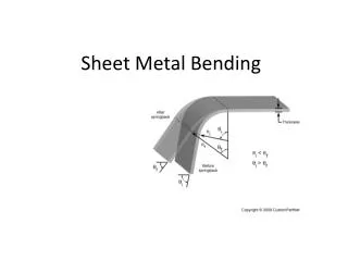
Neutral plane – no metal deformation here • Sheet metal parts are modeled in their folded state, but are fabricated from a flat sheet • Sheet metal deforms during bending • Transforming the folded model to the flattened state requires the use of bend allowances Inventor Does the “Heavy Lifting” in Sheet Metal Design Metal compresses on inside of bend Metal stretches on outside of bend
Inventor Does the “Heavy Lifting” in Sheet Metal Design • The Sheet Metal parameters are used to automatically calculate all bend allowances • Bend allowances are automatically added to all sheet metal features • Bend allowances are applied when creating a flat pattern Source of illustration: Inventor help files
Sheet Metal Parts Have Different Features and Workflow • Design of a Sample Part Create a sketch, then create a FACE from the sketch (note that “extrude” is not used)
Sheet Metal Parts Have Different Features and Workflow • Design of a Sample Part Create an open-sketch, then create a CONTOUR FLANGE from the sketch (note that Extrude & Unite are not used)
Sheet Metal Parts Have Different Features and Workflow • Design of a Sample Part Create another open-sketch, and another CONTOUR FLANGE
Sheet Metal Parts Have Different Features and Workflow • Design of a Sample Part Create a third open-sketch and CONTOUR FLANGE
Sheet Metal Parts Have Different Features and Workflow • Design of a Sample Part Create a closed-sketch, and create a CUT (similar to extrude and subtract)
Sheet Metal Parts Have Different Features and Workflow • Design of a Sample Part Create two FLANGES (requires no sketches)
Sheet Metal Parts Have Different Features and Workflow • Design of a Sample Part Create two HOLES (may use the standard Hole function or a PUNCH function for non-round cutouts)
Sheet Metal Parts Have Different Features and Workflow • Design of a Sample Part Create a FLAT PATTERN for the part
Sheet Metal Parts Are Like Other Parts in Many Respects • May be used in Assemblies • May be converted to a non-sheet metal part (if desired) • May be used to create drawings • May have standard part features added (not sheet metal-specific)
Modeling Sheet Metal Parts Summary • Several factors make it possible to optimize the design process for sheet metal parts • Most solid modelers have sheet metal-specific part features and modeling functions • Manufacturing information is included in sheet metal features • Sheet metal parts require two designs; one folded (3-D) and one flat (2-D)