The ILC Laser-wire system
The ILC Laser-wire system. Sudhir Dixit (s.dixit1@physics.ox.ac.uk). The John Adams Institute University of Oxford. The Laser-wire. A tool to measure e - /e + beam sizes/profiles all along accelerator complex (DR, Linac, BDS, IP)

The ILC Laser-wire system
E N D
Presentation Transcript
The ILC Laser-wire system Sudhir Dixit (s.dixit1@physics.ox.ac.uk) The John Adams Institute University of Oxford
The Laser-wire A tool to measure e-/e+ beam sizes/profiles all along accelerator complex (DR, Linac, BDS, IP) Thereby Estimation & Optimization of e-/e+ beamEmittance/Luminosity Features • Sub-micron resolution • Truly non-invasive • Probably the only viable diagnostic tool for high density ILC beams
Laser-wire principle Vertical scanning: y Horizontal scanning: x
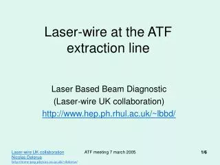
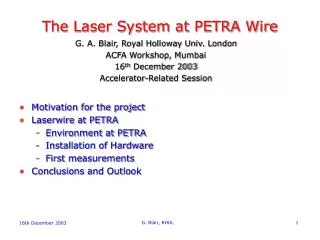
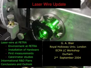
The Experimental LASER-WIRE Laser-wire at PETRA
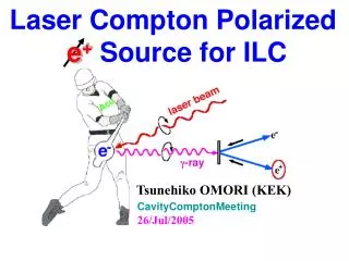
Laser-wire implementations: Our current status • LW system in operation at PETRA storage ring at DESY • e = 68 ± 3 m measured at 7 GeV • Upgradation planned with newly acquired injection • seeded Q-switched Nd:YAG laser (20Hz, 10 ns, 532 nm) • LW system hardware in place at ATF extraction line at KEK • e down to a few microns is to be measured • Mode locked laser system (357 MHz, 200 ps, 532 nm) is used • First Compton signal observed on 14th April • ILC Laser-wire system being planned at Oxford • Time resolved measurement within an ILC pulse (870 s) is aimed • Proof of principle will be tested at ATF-2 at KEK on ILC like pulses
ILC e-/e+ pulse structure ILC beam sizes
Guidelines on the choice of Laser for the ILC LASER-WIRE 1. Laser repetition rate, flaser flaser = femicrobunch (3 MHz, timing accuracy < 1 ps, Mode locked laser) Tmicro= e- bunch length (0.5 mm) = 2 ps (But may be relaxed to 10 ps) Tmacro = 870 s (Long pulse ML Laser) 2. Laser pulse duration, tmicro and tmacro m2 = e2 + L2 + L jitter2 + e jitter2 + …… We require, jitter < L < e [L 1 m] Gaussian profiles in space and time, TEMoo mode spatial coherence(M2 1) Focussing lens f# = 1.5-2 3. Laser spot size, L L M2 f# NC=P NeC h-1 c-2 -1/2 m-1/2 exp [- 0.5 (/m)2] For good accuracy, NC > 2000 and good energy stability. This requires P 10MW (100 J/10ps) 4. No. of Comptons (NC) & Laser peak power (P) We want, RL = 4 L2/ = x and L < Y Also we know, C reduces as L is reduced 5. Laser wavelength, L & Rayleigh Range, RL The net choice L = 250 nm – 500 nm
Laser design ( 1 m) for P = 50 MW@ f 3MHz Option 1: 500 J@10 ps@3 MHz; Pulse train power = 1.5 kW Option 2: 50 J@1 ps@3 MHz; Pulse train power = 150 W A laser master oscillator - power amplifier/s (MOPA) system is needed An attractive futuristic choice (option 2) A mode-locked fiber laser oscillator- preamplifier (1047/1053/1064 nm) system followed by high power DPSSL, Nd: YAG or Nd:YLF amplifier/s An alternative choice, already employed over the years (option 1) A diode/flashlamp pumped mode-locked Nd:YLF/Nd:YAG MOPA Choice on 2nd/4th harmonic crystal : LBO/BBO (250 nm – 500 nm)
Fiber lasers for Accelerator R & D High quality beams:Diffraction limited divergence, excellent beam profiles, very low pointing jitter Wide range of pulse- widths:100 fs to 10 ps Ultra-low noise jitter: 10s of fs Rep. rate:kHz to 10s of MHz Pulse energies:1 micro-joules (6 MHz, 1 ps pulses) to 1000 micro-joules (50 kHz, 200 fs pulses) Long diode life: 10 years Issues to be worked on more seriously: Exact rep. rate control and synchronization to external RF signal
Nd:YLF vs Nd:YAG Nd:YLF scores over Nd:YAG in terms of: Higher energy storage, lower wave-front distortions, better pointing, polarized output
Nd:YLF amplifier design Thermal fracture data For pulse train power = 1.5 kW And diode duty cycle = 2% Average laser power = 30 W, i.e. 4 W/cm << Frac. limit • The amplifier is pumped by 16/20 diode arrays distributed in 4/5 rings. • Each ring contains symmetrically located 4 diode arrays. • These 4/5 rings are rotated w. r. t each adjacent one suitably to maintain • excellent uniformity of pumping
On pump laser diodes for ILC LW power amplifier/s Pump diodes specifications:Modular design with relatively lower cost • Each diode module --- Standard 1 cm linear bar/array • Peak power of each bar --- 500 W at 5 to 10 Hz, at 800 nm • Total input power to amplifier --- 10 kW • Diode pulse duration --- 2 m-sec • Duty cycle --- 2 %
On non-linear optical frequency conversion: Generating harmonics • For 1047 nm to 524 nm:The best choice is Type I non-critically temperature phase matched LBO crystal • No walk- off - Long interaction lengths, Excellent circular beam • Gaussian profile with good coherence, High • Conversion efficiency > 70% • Large acceptance angle – 100 mrad • Large temperature bandwidth – 40 c at 1500 c • Damage threshold– 20 GW/cm2 at 1053 nm, a factor of 2 to 4 • larger than all other crystals e.g. KDP, KTP, BBO For 524 nm to 262 nm:The choice is limited to Type I critically phase matched BBO crystal Large walk-off, Elliptical output beam (needs correction) Conversion efficiency - 20 to 30%
ILC LW Mode-locked Fiber laser system specifications: Finer details Set repetition rate: 6.490 MHz (both for ILC & ATF-2) Repetition rate tune-ability: ± 100 kHz Resolution of tuning: <1 kHz Timing jitter: < 1ps at fixed rep. rate Pulse energy: 1 J Wavelength: 1047 nm Pulse width: 1ps Beam M2: < 1.1 Bandwidth: 1-2 nm Pointing stability: < 1 rad Polarization: Linear Energy stability: < 2% External trigger to RF Instrument version
Conclusion The laser system planned to developed at John Adams Institute, Oxford, has overlapping parameters with Laser polari-meter and photo-injector We can all mutually benefit and think about collaborations To the laser suppliers present here, We have requirements on Advanced Fiber lasers, Laser amplifiers, Special diodes, Laser Optics, etc Let us get in touch Thank you