Download
1 / 43
430 likes | 450 Vues
Laser Wire Update. G. A. Blair Royal Holloway Univ. London ECFA LC Workshop Durham 2 nd September 2004. Laser-wire at PETRA Environment at PETRA Installation of Hardware First measurements Calorimeter studies Intermational R&D Plans Conclusions and Outlook. Laser-wire Principle.

E N D
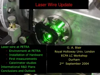
Laser Wire Update G. A. Blair Royal Holloway Univ. London ECFA LC Workshop Durham 2nd September 2004 • Laser-wire at PETRA • Environment at PETRA • Installation of Hardware • First measurements • Calorimeter studies • Intermational R&D Plans • Conclusions and Outlook G. Blair, RHUL
Laser-wire Principle • Scan finely focused laser beam through electron beam • Detection of Compton photons (or degraded electrons) as function of relative laser beam position • Challenges • Produce scattering structure smaller than beam size • Provide fast scanning mechanism • Achieve efficient signal detection / background suppression G. Blair, RHUL
Laserwire for PETRA PETRA parameters Laser parameters G. Blair, RHUL
Signal and Environment G. Blair, RHUL
Setup at PETRA G. Blair, RHUL
PETRA interaction chamber BPM viewport G. Blair, RHUL
The Laser • The laser was donated by CERN (it was used at LEP to measure beam polarization) • INd:YAG Q-switched system, running at 30 Hz • pulse energy measured: 40 mJ, power: 4 MW • synchronization to PETRA beam by triggering the Q-switch • transverse beam quality is modest (multimode) • measured spot size at IP: σL = (80 ± 10)μm Average profile Width=12 ns G. Blair, RHUL
79 ps 30 ps Longitudinal mode quality • The longitudinal structure is due to longitudinal mode beating – this was expected • The beating changes from shot to shot →Effective laser power 0.39 RMS 1 Peff T. Byatt, RHUL MSc G. Blair, RHUL
Removable mirror Photodiode Focusing lens Knife edge CCD CCD Resolution • Measure voltage of photodiode as knife edge steps through beam • Fit plot to Error function to deduce width of beam • Fit image on CCD for width of beam • Minimise both spots to fix positions of CCD and knife edge • Move focusing lens to change beam width at both points G. Blair, RHUL S. Malton
Pixel Number Pixel Number Number of Pixels Pixel Number Pixel Value Pixel Number AOI CCD Resolution (cont.) • CCD • 9.9m pixel width • Gaus + Gaus + Pol1 fit s1 • Knife Edge scan • Error function fit s2 G. Blair, RHUL S. Malton
CCD Resolution (cont.) • Linear fit • Linearity lost at large spot size • Gaussian background indistinguishable from signal • Single gaussian fit more accurate above 150 m G. Blair, RHUL S. Malton
Light transport G. Blair, RHUL
Lab Measurements at RHUL G. Blair, RHUL
Installation at PETRA G. Blair, RHUL CCDcamera
Detector • Requirements for detector material • short decay time (avoid pile up) • Small radiation length/Moliere radius • Cuboid detector crystals made of PbWO4 • 3x3 matrix of 18x18x150 mm crystals • Energy resolution better than 5% G. Blair, RHUL
Energy Calibration G. Blair, RHUL
Detector Calibration • Detector studies with DESY II testbeam • Beamline with electrons with energy from 450 MeV to 6 GeV • Combination of nine crystals in matrix • PMT has since suffered radiation damage and has been replaced G. Blair, RHUL
Results 04.12.03 Data Gaussian approximation of beam shape σm =(68 ± 3 ± 20) μm at low current σm =(80 ± 6 ± 20) μm at high current G. Blair, RHUL
Cosmics in Calorimeter – new PMT (2004) Before Run After Run K. Wittenburg G. Blair, RHUL
July 04 Data G. Blair, RHUL J. Carter
July 04 Data G. Blair, RHUL J. Carter
July 04 Data G. Blair, RHUL J. Carter
July 04 Data + BDSIM Simulation Exit angle: 24 mrad Num. photons: 3.90 Cut E >= 0.12 GeV G. Blair, RHUL J. Carter
July 04 Data + BDSIM Simulation Exit angle: 14 mrad Num. photons: 25.40 Cut E >= 0.16 GeV G. Blair, RHUL J. Carter
Laserwire DAQ and software • Complex problem • Essentially many single channels of a “normal” high energy experiment • CCDs : monitor laser beam size • BPM : electron beam position • Scanner : optics control and fast scanning • Calorimeter • Control and DAQ proving to be challenging • Lots of effort on technical level
DAQ structure • Examples of individual component readout • Each component responds to simple messages over TCP/IP • Data stored locally and merged later for analysis • Wide range of rates and data volumes are problematic • Future • Valuable experience for future laserwire experiments • Dedicated VME readout for experiments at ATF BPM TCP/IP CAL Local control CCD Control room
laser electrons Vertical Breadboard • To be installed this shutdown • Improve beam-finding capability • Allow 2-d scans • Increased diagnostics • Increased flexibility G. Blair, RHUL R. Senanayake
New Laser • Will aim for a • Q-switched • > ~ 10 MW per pulse • Good mode quality (M2 ~ 1.3?) • 1kHz rep rate • Diode pumped We are currently exploring options and contacting suppliers Hope to install early 2005 G. Blair, RHUL
Next steps • Full characterisation of laser: beam size, divergence, and power (stability) with slot scans and imaging techniques • Update all readout software, merge BPM and PMT software • Do more systematic scans with the fast scanner • Go to smaller spot sizes and reduce errors • Build second dimension (x) scanner. • New laser (Early 05?) • New vacuum vessel (Dec 04?) • New DAQ (Ongoing) • Start designing a complete laser-wire emittance measurement system for the LC BDS. • Look to ATF for micron-scale laserwire system G. Blair, RHUL
International ATF Laser-wire Project Extraction line: sigma_y ~ 5 m, intra-train fast scanning Clear additional technical challenges to PETRA experiment SLAC expertise will bolster the project • Very constructive discussions are ongoing • We have started to explore the technical details and preliminary designs • Exciting opportunity to establish a nucleus within the GDI. • Location found in ATF extraction line: G. Blair, RHUL
ATF LASER-WIRE DESIGN I. Ross SPECIFICATIONS E-beam parameters dimensions 50μm x 5μm bunch length 30ps bunch separation 2.8ns train length 60-300ns Laser requirements wavelength 530nm pulse power 100MW pulse duration 50ps pulse energy 5mJ pulse train energy 110-530mJ spot size 2μm (F/4 optic) depth of focus 35μm Scanning requirements angular scan range 0.5mrad (for 10 x 5μm spot and 50mm lens) scan rate at e-beam 0.1 – 0.5mrad/μs G. Blair, RHUL
ACTIVE SCANNING TECHNIQUES I. Ross • Scan Range in mrad Acceptable? Scan Rate in mrad/μs Acceptable? • Mirror 8.5 Yes 0.2 No • Acousto-optic 2.2 Yes 0.2 No • Electro-optic 1.5 Yes 150 Yes EO DEFLECTOR TELESCOPE BEAM TRANSPORT F/4 FOCUSING e-BEAM 5mJ/50ps @ 0.5μm 20 – 100 PULSES G. Blair, RHUL
I. Ross PASSIVE SCAN TECHNIQUE Use a Misaligned Multipass Cavity HR MIRROR λ/4 POCKELS CELL GATE F/4 FOCUSING POLARISING BEAMSPLITTER LASER e-BEAM 5mJ/50ps @ 0.5μm SINGLE PULSE 420mm (1.4ns) Mirror spacing determines the inter-pulse interval to match to 2.8ns Slight mirror tilt from perfect auto-collimation or slight shear of one lens gives scanning with equally spaced foci and a controllable spacing PC gate switches pulse into cavity Need to keep round-trip losses very low to ensure sufficient passes at sufficient power Other designs possible G. Blair, RHUL
Collaborators • DESY: S.Schreiber, K. Wittenburg, H-C Lewin, K. Balewski • BESSY: T. Kamps • RHUL: G.Blair, G. Boorman, RA: C. Driouichi, I. Agapov PhD: J. Carter, M. Price • UCL:RA: S. Boogert PhD: S. Malton • RAL: I. Ross • Oxford: B. Foster, A Reichold, D. Howell RA: N. Delerue + Mech+Elec tech. • CERN: (Laser, plus collaboration) • KEK: J. Urakawa, H. Hayano, K. Pavel, K. Kubo et al. Close contact with: • SLAC: (M. Ross, J. Frisch et al.) G. Blair, RHUL
Summary • Laser-wire project is very active • RA, Students working across detector R&D, accelerator physics, DAQ, optics, lasers, analysis, design – in a truly global environment. • PETRA laser-wire is being better understood – look forward to “routine” fast data taking… need more dedicated PETRA runs. • PETRA laser will be replaced, new vacuum vessel, DAQ … • ATF laser-wire is being planned and first designs are being studied. • Global collaboration will form, both at ATF and at PETRA – discussions currently underway. • New people joining the collaboration, starting in Autumn 2004. • Additional major effort in beam diagnostics simulation and incorporation into BDS (and other regions) design. • Room for wider collaboration and synergy – polarimetry, longitudinal profile, energy spectrometry. G. Blair, RHUL