Download
1 / 43
430 likes | 585 Vues
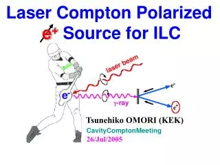
Laser Compton Polarized e + Source for ILC. Tsunehiko OMORI (KEK). CavityComptonMeeting 26/Jul/2005. ILC : International Linear Collider. DR. e - lineac. e + lineac. DRs. ~ 50 km. E cm = 500 - 1000 GeV. start experiment at ~2015. Polarized Beams play important role

E N D
Laser Compton Polarized e+ Source for ILC Tsunehiko OMORI (KEK) CavityComptonMeeting 26/Jul/2005
ILC: International Linear Collider DR e-lineac e+ lineac DRs ~ 50 km Ecm = 500 - 1000 GeV start experiment at ~2015 Polarized Beams play important role Suppress back ground Increase rate of interaction (if both beam pol) Solve Week mixing of final state
Two ways to get pol. e+ (1) Helical Undurator e- beam E >150 GeV Undulator L > 150 m (2) Laser Compton
Two ways to get pol. e+ (1) Helical Undurator e- beam E >150 GeV Undulator L > 150 m Our Proposal (2) Laser Compton
Why Laser Compton ? i) Positron Polarization. ii) Independence Undulator-base e+ : use e- main linac Problem on design, construction, commissioning, maintenance, Laser-base e+ : independent Easier construction, operation, commissioning, maintenance iii) Low energy operation Undulator-base e+ : need deccelation Laser-base e+ : no problem
ILC Undulator-base e+ Source 150 GeV 250 GeV 250 GeV Experiments
Today’s talk Proof-of-Principle demonstration at KEK-ATF Experiment at KEK, just finished 2. Concept of Laser Based Polarized e+ Source for ILC Simulation study & Plan of Experimental R/D
1. Experiment at KEK-ATF ATF: Accelerator Test Facility for ILC built at KEK Experiment done by Waseda-TMU-KEK collaboration 120 m
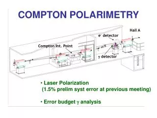
Experiment@KEK i) proof-of-principle demonstration ii) accumulate technical imformation: polarimetry, beam diagnosis, …
g-rayMeasured Asymmetry A= -0.93± 0.15 % A= 1.18± 0.15 % laser pol. = - 79 % laser pol. = + 79 % M. Fukuda et al., PRL 91(2003)164801
Ne+ = 3 x 10⁴/bunch Pol(expected) = 77% Asym (expected) = 0.95%
Measure e+ polarization : use Bremsstrahlung g-ray g-ray polarized e+ E = 40 MeV Pb conveter calculation
e+ polarization (e+ run) T. Omori et al., PRL 96 (2006) 114801 e+ beam spin e- spin in Iron A(R)= +0.60 ± 0.25% e+ beam spin e- spin in Iron A(L)= -1.18 ± 0.27% e+ beam spin non e- spin in Iron A(0)= -0.02 ± 0.25%
e+ run T. Omori et al., PRL 96 (2006) 114801 A = 0.90 ± 0.18 % Pol. = 73 %
We did e- run, also. e- run e+ run
e- polarization (e- run) e- beam spin e- spin in Iron A(R)= +0.78 ± 0.27% e- beam spin e- spin in Iron A(L)= -0.97 ± 0.27% e- beam spin non e- spin in Iron A(0)= -0.23 ± 0.27%
e- run A = 0.89 ± 0.19 %
Asymmetry Measurements e- run e+ run A = 0.90 ± 0.18 % A = 0.89 ± 0.19 % T. Omori et al., PRL 96 (2006) 114801
Summary of Experiment 1) The experiment was successful. High intensity short pulse polarized e+ beam was firstly produced. Pol. ~ 73 ± 15(sta) ± 19(sys) % T. Omori et al., PRL 96 (2006) 114801 2) We confirmedpropagation of the polarization from laser photons -> g-rays -> and pair created e+s & e-s. 3) We established polarimetry of short pulse & high intensity g-rays, positrons, and electrons.
2. Concept of Compton polarized e+ source for ILC Collaborating Institutes: BINP, CERN, DESY, Hiroshima, IHEP, IPN, KEK, Kyoto, LAL, NIRS, NSC-KIPT, SHI, and Waseda SakaeArakiYasuoHigashiYousukeHondaMasaoKurikiToshiyukiOkugi TsunehikoOmoriTakashiTaniguchiNobuhiroTerunuma, JunjiUrakawaXArtruMChevallier, VStrakhovenko, EugeneBulyakPeterGladkikhKlausMeonig, RobertChehabAlessandroVariolaFabianZomerFrankZimmermann, KazuyukiSakaueTachishigeHiroseMasakazuWashioNoboruSasaoHirokazuYokoyamaMasafumiFukuda KoichiroHiranoMikioTakanoTohruTakahashiHirokiSatoAkiraTsunemiand JieGao
Summer 2004 ITRP(International Technology Recommendation Panel) technology choice : cold LC (ILC) cold LC : super conduction RF cavity for accel.
Before Summer 2004 Conceptual Design for warm LC T. Omori et al., NIM A500 (2003) 232-252 Ne+=1.2x10¹⁰/bunch
After Summer 2004 Study Compton applied to a cold LC. New and Improved design Full use of slow repetition rate (5Hz)
ILC requirements 2x10¹⁰ e+/bunch (hard) 2800 bunches/train (hard) 5 Hz (we have time to store e + s) Strategy Old: Design for warm LC make positrons at once. both electron & laser beams: throw away T. Omori et al., NIM A500 (2003) 232-252 New: Design for cold LC (ILC) make positrons in 100 m sec. Electron storage ring, laser pulse stacking cavity : Re-use !!! positron stacking ring. Basic Idea: K. Moenig P. Rainer
Laser Pulse Stacking Cavity Fabry-perot Resonator Input laser (YAGlaser) Energy 1.2 mJ/bunch 3.077 nsec bunch spacing train length = 50 msec Cavity Enhancement Factor =500 Laser pulse in cavity 600 mJ/bunch single bunch in a cavity
ILC: International Linear Collider DR e-lineac e+ lineac DRs ~ 50 km
Schematic View of Whole System This part is necessary for ILC, no matter what e+ production scheme is chosen.
We also have Experimental R/D Plan for Comptom Pol. e+ Source Cavity-Compton
Plan: Exprmntl R/D at KEK Cavity Compton Collab.: Hiroshima-Waseda-LAL-Kyoto-CERN-KEK Make a fist prototype single cavity Lcav = 420 mm . Put it in ATF ring Nov. 2006
Summary of ILC source design Laser based scheme is good candidate of ILC polarized e+ source. We have new Idea make positrons in 100 m sec. Electron storage ring laser pulse stacking cavitys positron stacking ring (= e+ DRs) 1.6x10¹⁰ e+/bunch x 2800 bunches @ 5Hz with polarization ( ~ 60%) Some values are extrapolation from old design. We need detailed simulation. We plan to put prototype laser cavity in ATF.
Polarization Measurement e+ beam pol. (laser pol) e- spin in iron (magnet pol.) expected value (MC) ) Calculate A R A(R) : A(R) ~ + 0.95 % ) Calculate A A(L) : A(L) ~ - 0.95 % L ) Calculate A 0 non (Liner) A(0) : A(0) = 0
2.0 1.6 1.2 0.8 0.4 1.6 1.2 0.8 0.4 CO2 ring YAG ring Ng/electron/turn (in all energy of g-ray) 0 10 20 30 40 50 Turns 0 20 40 60 80 100 Turns Compton Ring (e- storage Ring) Average Ng/turn (in 23-29 MeV) CO2 : 1.78x10¹⁰ /turn YAG : 1.36x10¹⁰ /turn (average in 50 turns) (average in 100 turns)
i-th bunch on j-th DR turn -0.03 0.03 dEnergy/Energy e+ in a bucket Time -0.4 0.4 Longitudinal Pos. (m) e+ stacking in Damping Ring (simulation) 1st bnch on 1st trn 5th bnch on 5th trn 10th bnch on 10th trn T=0 ~110 msec before 11th bnch on 941st trn 11th bnch on 942nd trn 15th bnch on 946th trn ~10 msec before 21st bnch on 1882nd trn 20th bnch on 951st trn 100th bnch on 8479th trn ~10 msec + 110 msec ~20 msec ~100 msec + 110 msec 100 bnchs on 9410th trn 100 bnchs on 18820th trn stacking loss = 18% in total ~110 msec ~200 msec