Download
1 / 34
350 likes | 769 Vues
Chapter 3 Physical Components of a Network. 3.1 – Configuring a Network Interface Card 3.2 – Topologies 3.3 – Media Types 3.4 – Network Devices. Configuring a Network Interface Card. What is a NIC?.

E N D
Chapter 3Physical Components of a Network 3.1 – Configuring a Network Interface Card 3.2 – Topologies 3.3 – Media Types 3.4 – Network Devices
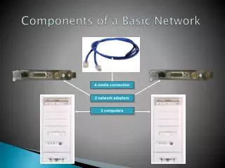
What is a NIC? • A network interface card (NIC) is a device that plugs into a motherboard and provides ports for the network media connections. • It is the component that interfaces with the local-area network (LAN). • The following things are important to consider when selecting a NIC: • The type of network • The type of media • The type of system bus
Setting the IP Address • In Windows, the IP address is manually entered into the TCP/IP properties dialog box. • The configuration box is used to set the address settings, or configurations that are entered into the host machine TCP/IP dialog box, which include: • An IP address • A subnet mask • Default gateway address • Domain Name System (DNS) • Windows Internet Naming Service (WINS)
DHCP Servers • DHCP is a software utility that automatically assigns IP addresses to PCs. • The computer running the software is known as a DHCP server. • DHCP servers assign the IP addresses and TCP/IP configuration information to computers configured as DHCP clients. • This dynamic process eliminates the need for manual IP address assignments.
Domain Name System • The Domain Name System (DNS) is used to translate the computer names such as www.cisco.com to the corresponding unique IP address. • Address translations are used each time the Internet is accessed. • The process of translating names to addresses is known as name resolution.
Domain Name System • The DNS server keeps records that map computer (host) names and their corresponding IP address. • These record types are combined in the DNS table. • When a host name needs to be translated to its IP address, the client contacts the DNS server. • A hierarchy of DNS servers exists on the Internet with different servers maintaining DNS information for their own areas of authority, called zones.
Default Gateway • A computer located on one network segment that is trying to talk to another computer on a different segment sends the data through a default gateway. • The default gateway is the near-side interface of the router. • It is the interface on the router to which the local computer network segment or wire is attached.
The Network Topology • The network topology defines the layout of the network. • It shows how devices on the network are interconnected. • Devices on the network are termed nodes. • A network has both a physical and a logical topology.
Physical versus Logical Topology • Physical topology shows the physical topology of a network, which refers to the actual physical layout of the devices and media.
Physical versus Logical Topology • Logical topology refers to the paths that signals travel from one point on the network to another. • These two terminologies can be confusing, because the word "logical" in this instance has nothing to do with the way the network appears to be functioning.
Identifying Network Topologies • Bus Topology • Commonly referred to as a linear bus, all the devices on a bus topology are connected by one single cable, which proceeds from one computer to the next. • This topology is rarely used and would only be suitable for a home office or small business with only a few hosts.
Identifying Network Topologies • Advantages of a bus topology: • The thinnet cabling it uses is quite inexpensive. • It uses less cable compared to other physical topologies like star or extended star • It works well for small networks • It does not need a central device, such as a hub, switch, or router • Disadvantages of a bus topology: • It results in slower access to the network and less bandwidth due to the sharing of the same cable by all devices • It is challenging to identify and isolate problems • A break at any point in the bus cable can disable the entire bus network • It needs terminators
Identifying Network Topologies • Star Topology • The star topology is the most commonly used architecture in Ethernet LANs and resembles spokes in a bicycle wheel. • A star topology generally costs more to implement than the bus topology because more cable is used and a central device is needed, such as a hub, switch, or router.
Identifying Network Topologies • Advantages of a Star Topology: • It is upgradeable, flexible, and reliable • It is easy to design and install • This topology makes diagnosing problems relatively easy since the problem is localized to one computer or device • This topology allows for more throughput than any other topology • Disadvantages of a Star Topology: • It requires a lot of cable to connect computers since a cable is required between each device and the central location. • It is more expensive to build because of the additional cost of cables and devices like hubs and switches that are needed to run between the central device and each computer
Identifying Network Topologies • Ring Topology • A frame, called a token, travels around the ring and stops at each node. • If a node wants to transmit data, it adds that data and the addressing information to the frame. • The frame continues around the ring until it finds the destination node, which takes the data out of the frame. • The advantage of using this method is that there are no collisions of data packets.
Identifying Network Topologies • Ring Topology • With single ring all the devices on the network share a single cable, and the data travels in one direction only. • With dual ring two rings allow data to be sent in both directions. • This creates redundancy (fault tolerance), meaning that in the event of a failure of one ring, data will still be transmitted on the other ring. • The 802.5 standard is the Token Ring access method that is used. • FDDI uses light instead of electricity to transmit data over a dual ring.
Identifying Network Topologies • The mesh topology connects all devices (nodes) to each other for redundancy and fault tolerance. • It is used in wide-area networks (WANs) to interconnect LANs and for critical networks. • The mesh topology is expensive and difficult to implement.
Identifying Network Topologies • The hybrid topology combines more than one type of topology. • When a bus line joins two hubs of different topologies, the configuration is called a star bus. • The bus line is used to transfer the data between the star topologies.
Networking Media • Networking media can be defined simply as the means by which signals (data) are sent from one computer to another. • This includes cable or wireless means. • There are a wide variety of networking media in the marketplace.
Twisted-Pair cable • Twisted-pair is a type of cabling that is used for telephone communications and most modern Ethernet networks. • A pair of wires forms a circuit that can transmit data. • The pairs are twisted to prevent cross talk. • Pairs of copper wires that are encased in color-coded plastic insulation are twisted together.
Twisted-Pair cable • Shielded twisted-pair (STP) cable combines the techniques of cancellation and twisting of wires with shielding. • Each pair of wires is wrapped in metallic foil to further shield the wires from noise. • The four pairs of wires are then wrapped in an overall metallic braid or foil. • STP reduces electrical noise from cable (crosstalk) and from outside the cable (EMI and RFI).
Twisted-Pair cable • Unshielded twisted-pair (UTP) has two or four pairs of wires. • It relies solely on the cancellation effect produced by the twisted wire pairs to limit signal degradation caused by electromagnetic interference (EMI) and radio frequency interference (RFI). • UTP is the most commonly used cabling in Ethernet networks.
Fiber-Optic Cable • Fiber-optic cable is a networking medium that is capable of conducting modulated light transmissions. • To modulate light is to manipulate it so that it travels in the way that it transmits data. • It refers to cabling that has a core of glass or plastic (instead of copper), through which light pulses carry signals.
Wireless • Wireless networks use radio frequency (RF), laser, infrared (IR), and satellite/microwaves to carry signals from one computer to another without a permanent cable connection. • Wireless signals are electromagnetic waves that travel through the air. • No physical medium is necessary for wireless signals. • Mobile phones are a common application of wireless.
Hubs and Repeaters • Typical LAN devices include repeaters, hubs, bridges, switches, and routers. • A repeater receives the signal, regenerates it, and passes it on. • Repeaters are used mainly at the edges of networks to extend the wire so more workstations can be added.
Hubs and Repeaters • Using a hub changes the network topology from a linear bus, where each device plugs directly into the wire, to a star. • Data arriving over the cables to a hub port is electrically repeated on all the other ports connected to the same Ethernet LAN, except for the port on which the data was received. • Hubs come in three basic types: • Passive • Active • Intelligent
Bridges and Switches • Bridges and switches operate at the data link layer of the OSI model. • The function of the bridge is to make intelligent decisions about whether or not to pass signals on to the next segment of a network. • When a bridge sees a frame on the network, it looks at the destination MAC address and compares it to the forwarding table to determine whether to filter, flood, or copy the frame onto another segment.
Bridges and Switches • Switches learn certain information about the data packets that they receive from computers on the network. • They use this to build forwarding tables to determine the destination of data being sent by one computer to another on the network. • They help segment a network and reduce network traffic congestion by limiting each port to its own collision domain.
Routers • Routers operate at the Network layer of the OSI model. • They are slower than bridges and switches but make "smart" decisions on how to route packets received on one port to a network on another port. • Routers are capable of segmenting the network. • Routers are capable of segmenting a network into multiple collision domains as well as into multiple broadcast domains.
Routers • Routers can be computers with special network software installed on them or they can be other devices built by network equipment manufacturers. • Routers contain tables of network addresses along with optimal destination routes to other networks.