Download
1 / 11
110 likes | 241 Vues
Activities on MAPs at Hamburg (DESY/University Hamburg. studies to optimise mechanical layout cooling studies for vertex detector plans for switching power for testbeam studies radiation damage due to electrons. Studies to optimise mechanical layout. (C. Muhl).

E N D
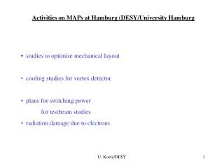
Activities on MAPs at Hamburg (DESY/University Hamburg • studies to optimise mechanical layout • cooling studies for vertex detector • plans for switching power • for testbeam studies • radiation damage due to electrons U. Koetz/DESY
Studies to optimise mechanical layout (C. Muhl) Find best material and design ladder support assumption: sensor will be thinned down to 30 m ! goal: additional material should be of about same thickness in X0 Material search: light, low Z, stiff, benign, available, ….. best choices for given stiffness along ladder in terms of X0 Be, CVD diamond, carbides of Si and Bif foamed properties of foamed ceramics calculable foamed SiC is available first structure produced search for B4C continues U. Koetz/DESY
b assume E • I = 300,000 Nmm2 , b = 24 mm % Xo U. Koetz/DESY
First structure made from SiC 115 mm 25 mm SiC structure together with parts for cooling tests SiC foam produced by CVD technology groove for micro capillary already included still factor of 10 too much material : 1.5 g U. Koetz/DESY
Preparations for cooling tests (J. Hauschildt) components for first cooling tests assume:1 kW power dissipation for full VXD earlier studies: gas cooling excluded, too high velocities use evaporative cooling (see ATLAS) goal: keep temperature stable to ±0.1o C over VXD • setup evaporative cooling system • study single structure with approx. 6 W power temperature distribution,… • develop prototype with full “chips” distribution • over the volume of the VXD and full power • dissipation support 30 m glass with Al strips for power dissipation 300 m capillaries U. Koetz/DESY
final choice C3F8 hardware for evaporative cooling exists controls and temperature sensing are being designed start of cooling tests in January 2004 U. Koetz/DESY
300 m 70 m cooling channel Thinning of silicon Collaboration with TU Hamburg-Harburg - Microsystem technology - Si <111> thinning by plasma etching first samples by end of this week U. Koetz/DESY
Mimosa aux board IRF7455 Mimosa board Insert in cable controls Idea for power switching or similar power pulser Spice simulation of DC power consumption Ron ~ 0.007 Ohm switching time < 100 ns U. Koetz/DESY
Preparation for testbeam studies one Mimosa 5 + readout card from Strasbourg available at DESY and working testbeam: Si telescope in 6 GeV electrons, resolution ~ 10 m solenoidal magnet B = 1 T, wrong field direction for MAPS dipol magnet B = 2 T , proper field direction DAQ to be modified for testbeam application preparations underway } Collision TPC – MAPS ? source tests in 5 T solenoid are planned as well U. Koetz/DESY
900 MeV e- irradiation of different silicon substrates Charge collection efficiency ( particles from a 244Cm source) Depletion voltage vs. fluence • 900 MeV electron beamof the LINAC injector at Elettra (Trieste, Italy) • Tested devices: p+/n-/n+ diodes from CiS (Erfurt, Germany) • Standard (FZ) and oxygenated (DOFZ) float-zone:resistivity~3-4 kWcm, [O]DOFZ~1.2x1017 cm-3 • Epitaxial (EPI):50 μm thick epitaxial layer (r~50 Wcm) grown by ITME (Warszawa, Poland) on 300 μm thick, low resistivity (~0.01 Wcm) Czochralski substrate • All measurements performed after thermal annealing for 8 min @ 80°C • Substrate type-inversion observed in FZ and DOFZ, but not in EPI devices (higher pre-irradiation Neff and high oxygen concentration, [O]EPI~0.9x1017 cm-3) • Charge collection efficiency not significantly affected U. Koetz/DESY from Devis Contarato/Uni HH