Download
1 / 23
230 likes | 409 Vues
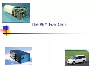
Boundary Layer Analysis of Flow through a Single Channel PEM Fuel Cell. Viscous Flows Dr. Kirk By Chris Jojola. Introduction. How They Work. Uses. Small voltage for each cell. They must be stacked in series for automotive purposes. My Research.

E N D
Boundary Layer Analysis of Flow through a Single Channel PEM Fuel Cell Viscous Flows Dr. Kirk By Chris Jojola
Uses • Small voltage for each cell. • They must be stacked in series for automotive purposes.
My Research • The effect of channel path on PEM fuel cell performance. • Several different configurations, including square, serpentine, and spiral. • For this project the serpentine configuration was chosen.
Sample Results ~ 2 million cells
Problem • The goal of this project was to resolve the boundary layer along the inside of the channels to improve the accuracy of computations. • Once accomplished, the next goal was to determine if the improved accuracy was worth the extra computational time and power.
Splitting the Problem in Two • The cell has nearly 2 million cells. • Adding more points and using Fluent’s PEM module could take an entire day per case. • Instead I performed two different tests for three cases (6 total)
Part One • For the first test, I reduced the cell to a single channel and ran hot air through it.
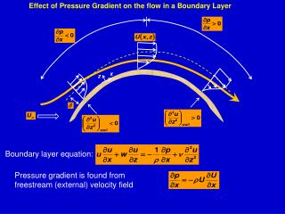
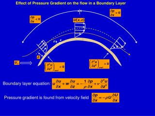
Part One – Cont. • The goal was to observe the change in velocity, temperature, and pressure profiles. • The overall pressure drop was also taken into consideration.
Part Two • The second part was to reduce the cell to a single sweep and run using the full PEM module. • The velocity, pressure, etc. were also observed, but the main goal was to see how the change affected electrical parameters such as cell voltage and current density.
Part Two – Cont. Course Original Fine
Results • The results for both tests showed that the grid change did very little to improve the accuracy of the test.
Results – Part One • Grid refinement had an almost negligible change on the pressure drop over the entire channel. • However, the time needed for convergence increased dramatically (close to 50%)
Course Original Fine Results – Part One Cont. Pressure Velocity Velocity (Zoom)
Results – Part Two • The grid refinement on the small section of the cell running the full PEMFC software led to less than 1% change in pressure and current density. • Since two channels had a significant number of cells added, the computational time increased dramatically for the refined grid.
Results – Part Two Cont. Course Original Fine
Conclusions • The boundary layer within the anode and cathode channels is sufficiently large to be captured by the current grid. • Increasing the cell count would add considerable computing with a minimal effect on the results.