Download
1 / 32
320 likes | 450 Vues
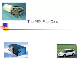
The PEM Fuel Cells. Nafion Thermal Behavior. Silicon Oxide/Aciplex 1004. 130. o. C. Nafion 115. 1.0. 80. o. C. o. 130. C. 0.8. 0.6. Cell Potential / V. 0.4. 0.2. 0.0. 0. 200. 400. 600. 800. 1000. 1200. 1400. 1600. 1800. Current Density / mA cm 2.

E N D
Nafion Thermal Behavior Silicon Oxide/Aciplex 1004 130 o C Nafion 115 1.0 80 o C o 130 C 0.8 0.6 Cell Potential / V 0.4 0.2 0.0 0 200 400 600 800 1000 1200 1400 1600 1800 Current Density / mA cm2
Is the Metal Oxide Phase Water Retentive? • The composite typically contains 3-6 wt% metal oxide. • TGA indicates the same water content and dehydration temperature for pure Nafion and the composite. • The conductivity of the composite measured in a mechanically unconstrained environment is the same or slightly worse than the conductivity of pure Nafion. The metal oxide is not simply providing a water retentive or hydrated interface.
If it’s not a question of direct dehydration, then what is occurring? • First, we will seek a molecular picture. • Then, we will attempt to make connections between our understanding of the molecular structure and bulk materials properties.
Effect of Metal Oxide Identity on Membrane Performance 1.0 o 130 C (Degussa-Huls) 2 /g (R - 0.18) TiO ; 21nm; 50 m 0.8 2 2 SiO ; 20nm; 90 m /g (R - 0.21) 2 2 Al O ; 13 nm; 100 m /g (R - 0.76) Cell Potential / V 2 3 Recast Nafion Control (R - 0.5) 0.6 0.4 0.2 0 500 1000 1500 -2 Current Density / mA cm
Interfacial Chemistry is Critical 1.0 (AA)/Recast Nafion; 130˚C TiO2 unmodified (R - 0.50) 0.8 silylated (R - 0.29) H SO , HNO , "degreased" (R - 0.25) 2 4 3 Cell Potential / V 0.6 0.4 0.2 0 200 400 600 800 1000 1200 1400 1600 -2 Current Density / mA cm
75% Relative Humidity 125µ Film 3 atm pressure 40 ml/min
Potential Chemical Interactions -----CF----- -----CF----- SO3- HO O=S=O OH O Metal Oxide Metal Oxide Ti ----CF2-CF2--- OH OH Metal Oxide
Temperature Programmed Decomposition (TG-MS) of Nafion 117 Thermal decomposition of Nafion C3F5+ 2nd step CFO+ - 1st step H2O H2O SO2 SO2 C3F5+ CFO+ H2O
TG-MS Profile of Nafion/TiO2 Composite Membranes TiO2 Thermal decomposition of Nafion 3rd step C3F5+ 2nd step CFO+ - 1st step HO H2O SO2 C3F5+ CFO+ SO2 H2O
TPD-MS profiles of Nafion/Inorganic composite membranes - SO2 (m/z 64) CFO (m/z 47) H2O (m/z 18) C3F5 (m/z 131)
Molecular Model • Crosslinking controls the mechanical properties of the polymer • Glass transition temperature • Bulk rigidity – better water retention under stress load
Order-Disorder Transition Crystalline Heat Disordered Self Assembled
Membrane Mechanical Properties Affect Cell Response Ionic inclusions swell with water uptake, requiring the membrane to push the electrodes apart.
Stress-Strain Response 6 5.5x10 6 5.0x10 ) 6 4.5x10 2 6 4.0x10 Metal Oxide Composite Nafion 112 6 3.5x10 Stress (N/m 6 3.0x10 6 2.5x10 6 2.0x10 6 1.5x10 6 1.0x10 5 5.0x10 0.0 0 20 40 60 80 100 120 140 160 180 200 Strain(%)
Membrane Swelling Carbon support The membrane is in contact with the catalyst support particles. membrane Applied pressure enhances the membrane/catalyst contact. Additional pressure further increases the membrane/catalyst contact. However, the larger pressure forces water out of the membrane.
Hydrogen Crossover 1000 4.0 ) 2 950 3.0 900 2.0 Open Circuit Voltage (mV) Crossover Current (mA/cm 850 1.0 800 0.0 125µm 40µm Composite 40µm Membrane
What Role Does the Metal Oxide Play? • Increased Tg allows maintenance of hydrated proton conduction paths at elevated temperatures. • Improved mechanical rigidity allows for dimensional stability under conditions where water content of the membrane may be changing. • Maintains good catalyst contact on deswelling • Eliminates water loss on swelling.
Carbon Monoxide Tolerance o Nafion 115 - 80 C Pt Anode 1.0 w/o CO w/100 ppm CO 0.9 o TiO - 130 C Pt/Ru Anode 0.8 2 w/100 ppm CO w/500 ppm CO 0.7 Cell Potential / V 0.6 0.5 0.4 0.3 0.2 0 200 400 600 800 1000 1200 1400 1600 -2 Current Density / mA cm
Summary • High Temperature Nafion Based PEM Fuel Cells overcome several limitations associated with current cell design • Addition of a metal oxide phase affects the mechanical properties of the membrane: • Increased Tg • Improved gas barrier • Mitigation of swelling/deswelling effects
Bonus Material (It’s not electrochemistry, but it is interesting) So, How Does One Store Hydrogen on the Run?
Safety For mobile applications range & power should be maintained. 5-10Kg of H2 needed for a 65-75kW engine. H2 feed rate is ~1000 liters/minute Weight Effective Density of Hydrogen Volume Requirements Size Geometry Refill Availability Recharge rate. Cost Storage Issues
Storage Options • Standard steel tanks (2000-5000psi) • Known technology. • Good Safety Record • Subject to hydrogen imbrittlement • Forms projectiles if structure is breached • Tanks are challenging to fill because hydrogen heats upon expansion • Heavy • Storage capacity is only 0.5-1% by weight • Poor volumetric storage due to non-ideality of hydrogen:
Storage Options • Composite Tanks (~10,000psi) • High storage capacity: • Light weight • Can store 7% H2 by weight! • Does not fragment upon failure • Cost
Generation on the fly: in-situ or ex-situ reforming of hydrocarbon fuels using an on-site reformer. Energy density of gasoline Easy access to fuel (gasoline stations) Systems integration is poor No carbon mitigation. Solid-state storage by intercalation (metal hydrides, carbons) Safe Heavy Expensive Chemical thermodynamics and kinetics are difficult Significant heating is required to release the hydrogen ∆H losses up to 30% are typical with operating temperatures of 200-300C. Tank filling is very exothermic Chemical kinetics are a difficult to handle Storage Options
Chemical Hydrides “Hydrogen on Demand” (Sodium Borohydride) Not flammable High Effective hydrogen pressure (~7000psi) Low Volume Simple system Chemical Safety Recyclable Cost?? Storage Options