Composites. An overview
Composites. An overview. For CME/MSE 404G. Composite examples Fiber-reinforced composites Matrices and fibers Effects of fiber orientation. Multiple lamellae structures Fiber/matrix wetting Composites manufacturing Typical composite design challenges. Outline.


Composites. An overview
E N D
Presentation Transcript
Composites. An overview For CME/MSE 404G cme/mse 404g composite overview
Composite examples Fiber-reinforced composites Matrices and fibers Effects of fiber orientation Multiple lamellae structures Fiber/matrix wetting Composites manufacturing Typical composite design challenges Outline cme/mse 404g composite overview
Composite examples.Properties, performance, processing, structure Composite push rod Tires Brake shoes cme/mse 404g composite overview
Composite Push Rod For Automobiles Collin. MSE 556. Spring, 2006 • Properties • High compressive and tensile strength along the axial direction; (secondary) stiff with respect to torsion, bending and shear; temperature resistance; chemical resistance to lubricants and fuel gases • Performance • Failure mechanisms: overloading (tensile/compressive), torsion, off axis loading, fatigue, crack growth/delamination less of a concern • Processing • In order to construct the composite push rod, the bar is first constructed and then the ends are bonded. The bar is constructed of a plurality of layers of sheets of epoxy impregnated, longitudinally oriented fiber material that are wrapped around a removable mandrel. The sheets of longitudinally oriented fiber material form the inner portion of the push bar and a single outside sheet of epoxy impregnated, woven fiber material that is wrapped around the sheets of longitudinally oriented fiber material forms the outside portion of the bar. The sheets of fiber material are comprised on a fiber, such as carbon, Kevlar, or glass, and the fiber material is resin impregnated with a thermosetting, high temperature, toughened epoxy. Once all of the layers of fiber material are wrapped together, they are heated and compressed to thermo-set the layers into a single composite bar. The mandrel is then removed, leaving a central opening in the bar where the mandrel was located. The ends of the composite bar are then cut to the proper shape and the mating surfaces of the metal end fittings are bonded to the ends of the composite bar via epoxy, thereby completing construction of the composite push rod. • Structure • Composite push rods are lighter weight replacements for metallic push rods in use between a cam shaft and a valve rocker in internal combustion engines. These composite push rods are constructed of a bar that is made of carbon fiber. These composite push, bars generally have flat ends to which rounded metal end fittings are bonded, usually by some type of epoxy or adhesive. The composite push rod then attaches to the cam shaft and valve rocker via these rounded metal end fittings. cme/mse 404g composite overview
Performance Processing Tires 1. The process begins with the mixing of basic rubbers with process oils, carbon black, pigments, antioxidants, accelerators and other additives, each of which contributes certain properties to the compound. These ingredients are mixed in giant blenders called Banbury machines operating under tremendous heat and pressure. They blend the many ingredients together into a hot, black gummy compound that will be milled again and again. 2. This compound is fed into mills which feed the rubber between massive pairs of rollers,feeding, mixing and blending to prepare the different compounds for the feed mills, where they are slit into strips and carried by conveyor belts to become sidewalls, treads or other parts of the tire. Still another kind of rubber coats the fabric that will be used to make up the tire's body. Many kinds of fabrics are used: polyester, rayon or nylon. 3. Another component, shaped like a hoop, is called a bead. It has high-tensile steel wire forming its backbone, which will fit against the vehicle's wheel rim. The strands are aligned into a ribbon coated with rubber for adhesion, then wound intoloops that are then wrapped together to secure them until they are assembled with the rest of the tire. Radial tires are built on one or two tire machines. The tire starts with a double layer of synthetic gum rubber called an innerliner that will seal in air and make the tire tubeless. 4. Next come two layers of ply fabric, the cords. Two strips called apexes stiffen the area just above the bead. Next, a pair of chafer strips is added, so called because they resist chafing from the wheel rim when mounted on a car. The tire building machine pre-shapes radial tires into a form very close to their final dimension to make sure the many components are in proper position before the tire goes into the mold. 5. Now the tire builder adds the steel belts that resist punctures and hold the tread firmly against the road. The tread is the last part to go on the tire. After automatic rollers press all the parts firmly together, the radial tire, now called a green tire, is ready for inspection and curing. 6. The curing press is where tires get their final shape and tread pattern. Hot molds like giant waffle irons shape and vulcanize the tire. The molds are engraved with the tread pattern, the sidewall markings of the manufacturer and those required by law. Tires are cured at over 300 degrees for 12 to 25 minutes, depending on their size. As the press swings open, the tires are popped from their molds onto a long conveyor that carries them to final finish and inspection. **This is traditional technique by goodyear, new automated processes are used by pirelli. Optimal performance is achieved by proper use and maintenance. Understanding the labeling or sidewall markings is key. Example: P215/65R15 89H P: passenger, vs. LT that has higher ply ratings 215: width 65: aspect ratio R: radial, vs. belted construction or diagonal construction 15: diameter of wheel 89: load index--indicates the max weight each tire can support H: speed rating—measurement of top safe speed the tire can carry a load under specified conditions. (worst to best: Q,S,T,U,H,V,Z,W,Y) *a higher rated tire will give better traction and improved steering response at 50 mph. Also consider: -Max. cold inflation (in psi) see images below!**very important -Load limit (redundant to load index) -treadware grading--how long the tread will last -traction grading—indicates tires ability to stop in a straight line on wet pavement -temp grading—min speed a tire will not fail at high temp. cme/mse 404g composite overview References: 1010tires.com, goodyeartires.com, us.pirelli.com
Properties Structure Typical phsyical properties of a universal tire Weight % for Passenger Tire Hardness (Shore A,D) - measures resistance to indentation. A "soft" elastomer & D for "harder" materials.Compression Modulus (psi) - force required to achieve a specific deflection, typically 50% deflection, predicts a material's rigidity or toughness.Tear Strength (pli) - measures the resistance to growth of a nick or cut when tension is applied to a test specimen, critical in predicting work life Tensile Strength (psi) - ultimate strength of a material when enough force is applied to cause it to break, with elongation and modulus, tensile can predict a material's toughness.Ultimate Elongation (%) - percent of the original length of the sample measured at point of rupture. 300% Modulus (psi) - stress required to produce 300% elongation. Bayshore Rebound (%) - resilience of a material. ratio of returned energy to impressed energy. predicts rolling resistance.Compression Set (%) - measures the deformation remaining in an elastomer after removal of the deforming force. In combination with rebound, set values predict an elastomer's success in a dynamic application. cme/mse 404g composite overview http://www.p2pays.org/ref/11/10504/html/intro/tire.htmwww.superiortire.com
Brake Shoes Performance Properties Processing Structure cme/mse 404g composite overview
Fiber-reinforced composites cme/mse 404g composite overview
Applications. Fiber-reinforced composites • Aircraft and military – F14 horizontal stabilizers, 1969. • Space – boron fiber-reinforced aluminum tubes, Kevlar/epoxy pressure vessels • Automotive – body (Class A finish, polyurethanes), chassis (Corvette rear leaf spring), engine • Sporting goods –weight redution • Marine – boat hulls, decks, bulkheads cme/mse 404g composite overview
Fiber alignment • Unidirectional, continuous • Bidirectional, continuous • Unidirectional, discontinuous • Random, discontinuous Fibers + matrix + coupling agents + fillers lamina cme/mse 404g composite overview
Matrix and fiber properties cme/mse 404g composite overview
Resin Properties cme/mse 404g composite overview
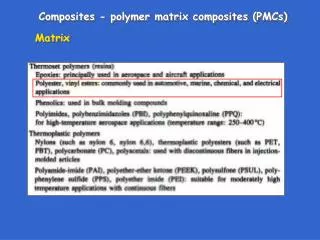
Common commercial matrices • Thermosets: epoxies, polyester, vinyl ester, phenolics, polyimides • Thermoplastics: nylons, linear polyesters, polycarbonate, polyacetals, polyamide-imide, PEEK, PSul, PPS, PEI • Metallic – Al alloys, Ti alloys, Mg alloys, copper alloys, nickel alloys, SS • Ceramic – aluminum oxide, carbon silicon carbide, silicon nitride cme/mse 404g composite overview
Fiber properties • Specific gravity • Tensile strength, modulus • Compressive strength, modulus • Fatigue strength • Electrical, thermal conductivity • cost cme/mse 404g composite overview
Fiber Properties cme/mse 404g composite overview
Effect of fiber diameter on strength Fiber that are formed by spinning processes usually have increased strength at smaller diameters due to the high orientation that occurs during processing. cme/mse 404g composite overview
Common commercial fibers • Glass • Graphite • Kevlar 49 • PE (Spectra) • Boron • Ceramic – SiC, Al2O3 cme/mse 404g composite overview
Effects of fiber orientationContinous, aligned fibers. Morphology and mechanical properties cme/mse 404g composite overview
Representative Element of an Aligned-Fiber Bundle cme/mse 404g composite overview
(a) Micrograph of a carbon epoxy composite(b) square packing array cme/mse 404g composite overview
Stiffness of a unidirectional carbon epoxy laminate as a function of test angle relative to fiber direction cme/mse 404g composite overview
Effect of average fiber volume Vf on the axial permeability of an aligned-fiber bundle cme/mse 404g composite overview
Fiber volume fraction (Vf) cme/mse 404g composite overview
Viscosity change and cure cycle for graphite/epoxy composite (Hercules AS4/3501-6) In general, matrix viscosity increases with temperature until the polymer cures to the gel state. Above this temperature, local chain motion is restrained by crosslinks, and additional curing for higher crosslinking can require long “post-cure” times. cme/mse 404g composite overview
Fiber volume fraction Vf versus processing viscosity, µ. common polymer matrix systems cme/mse 404g composite overview
Multiple lamellae structures Design issues cme/mse 404g composite overview
Linear Fiber Structure [0/90/0] cme/mse 404g composite overview
Top and side views of woven (interlaced) fibers cme/mse 404g composite overview
Combination fiber structure showing linear fibers and interlacing through the thickness cme/mse 404g composite overview
Illustration of idealized, linear 3D fiber structures cme/mse 404g composite overview
Stacking sequence of a (0/90±45)s quasi-isotropic layup Symmetric lay-ups prevent warping under stress, thermal expansion cme/mse 404g composite overview
In-plane stiffnesses of various-ply geometries as a function of test angle, relative to the on-axis stiffness of a unidirectional laminate cme/mse 404g composite overview
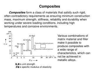
Relative modulus vs. fiber volume fraction Range of obtainable elastic moduli for various composites normalized by the fiber modulus, Ef, versus the fiber volume fraction (configuration indicated) cme/mse 404g composite overview
Fiber/matrix wetting Wetting of the fibers by the matrix material cme/mse 404g composite overview
Illustration of spontaneous wetting (a) at t=t0 and (b) at t>t0 Matrix material is often added to fiber assemblies, and needs to wet the fibers in order to prevent void formation. cme/mse 404g composite overview
Surface Energies cme/mse 404g composite overview
Resin infiltration of unidirectional glass fibers in [0/90] layup showing the formation of voids Resin has wicked into several orthogonal lamellae, forming voids (bubbles). The slight refractive index difference between fiber and matrix allows the fiber directions to be observed. cme/mse 404g composite overview
Composites processing Hand lay-up,+/- molds, filament winding, pultrusion, resin transfer molding, vacuum forming cme/mse 404g composite overview
Schematics of (a) hand layup and (b) mechanically assisted hand layup cme/mse 404g composite overview
Several bagged composite parts being rolled into the autoclave for cure cme/mse 404g composite overview
Schematic of the filament winding process cme/mse 404g composite overview
Examples of unstable fiber paths in the filament winding process cme/mse 404g composite overview
Filament winding of a rocket motor tubee.g., booster rocket cme/mse 404g composite overview
Schematic of automatic tow placement process showing seven axes of motion cme/mse 404g composite overview
Automatic fiber placement of the V-22 aft fuselage section on the Cincinnati-Milacron seven-axis CNC fiber placement machine cme/mse 404g composite overview
Inside view of the fiber placed V-22 fuselage section secured with stiffeners cme/mse 404g composite overview
Schematic of the pultrusion process cme/mse 404g composite overview
Examples of pultruded part cross sections including airfoil shapes and structural skins and stiffeners cme/mse 404g composite overview
Examples of pultruded part cross sections including airfoil shapes and structural skins and stiffeners cme/mse 404g composite overview
Schematic of the resin transfer modeling process showing (a) fiber preform and (b) resin injection into fiber preform cme/mse 404g composite overview