Iterative Timing Recovery
Iterative Timing Recovery. Aleksandar Kavčić Division of Engineering and Applied Sciences Harvard University based on a tutorial by Barry, Kavčić, McLaughlin, Nayak & Zeng And on research by Motwani and Kavčić. Outline. Motivation Timing model Conventional timing recovery

Iterative Timing Recovery
E N D
Presentation Transcript
Iterative Timing Recovery Aleksandar Kavčić Division of Engineering and Applied Sciences Harvard University based on a tutorial by Barry, Kavčić, McLaughlin, Nayak & Zeng And on research by Motwani and Kavčić
Outline • Motivation • Timing model • Conventional timing recovery • Simple iterative timing recovery • Joint timing and intersymbol interference trellis • Soft decision algorithm • Performance results • Conclusion • Future challenge: capacity of channels with synchronization error
Motivation • In most communications (decoding) scenarios, we assume perfect timing recovery • This assumption breaks down, particularly at low signal-to-noise ratios (SNRs) • But, turbo-like codes work exactly at these SNRs • Need to take timing uncertainty into account
Xn* Xn Yn S R Channel t Perfect timing
Xn YL S R Channel t System Under Timing Uncertainty difference between transmitter and receiver clock basic assumption: clock mismatch always present
1 -T 0 T 2T 3T t A More Realistic Case Sample instants: kT kT+k
t t Properties of the timing error • Brownian Motion Process (slow varying). • Discrete samples form a Markov chain.
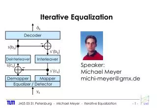
Timing recovery strategies turbo equalization (inner loop) a) c) timing recovery symbol detection timing recovery symbol detection decoding decoding free running oscillator free running oscillator iterative timing recovery (outer loop) turbo timing/equalization b) d) turbo equalization timing recovery symbol detection joint soft timing recovery and symbol detection decoding decoding free running oscillator free running oscillator
Strategy to solve the problem • Set up math model for timing error (Markov). • Build separate stationary trellis to characterize the channel and source. • Form a full trellis. • Derive an algorithm to perform the Maximum a posteriori probability (MAP) estimation of the timing offset and the input bits
1 -T 0 T 2T t 3T Quantizing the Timing Offset Uniformly quantize the interval ((k-1)T, kT] to Q levels.
0 θ 2θ δ -2θ -θ δ Math Model for Timing Error State Transition Diagram: State Transition Probability:
1 t -T 0 T 2T 3T States for Timing Error Semi-open segment : ((k-1)T, kT]: Q 1-sample states: 1i i=1, 2, …, Q 1 deletion states: 0 1 2-sample state: 2
k Q = 5 T/Q 4 5 6 7 8 9 10 11 12 13 14 15 k 0 0 1 2 3 -T/Q -2T/Q -3T/Q -4T/Q -5T/Q = -T Example: timing error realization
0 T 2T 3T 4T 5T 6T 7T 8T 9T 10T 0th interval 1st interval 2nd interval 3rd interval 4th interval 5th interval 6th interval 7th interval 8th interval 9th interval 10th interval 15 15 14 14 15 0 2 0 11 11 12 t 0-0 T- 1 2T- 2 3T- 3 4T- 4 5T- 5 6T- 6 7T- 7 8T- 8 9T- 9 0 11 12 13 14 15 2
Single trellis section 0 0 11 11 12 12 13 13 14 14 15 15 2 2
1, -1 -1, -1 -1, -1 -1, 1, -1 1, 1 -1, -1 -1, -1 1, 1 1, -1 -1, -1, -1 -1, -1 -1, 1, -1 1, 1 -1, -1 -1, -1 -1, 1, 1 -1, 1 -1, 1 -1, 1 -1, 1 Source Model Second order Markov chain
Full states set: Full Trellis Total number of states at each time interval: Trellis length = n (block length). (note that each branch may have different number of outputs).
c) joint ISI-timing trellis (-1,-1,0) (-1,-1,0) … … … (-1,-1,11) (-1,-1,11) (-1,1,11) (-1,1,11) (1,-1,11) (1,-1,11) b) ISI trellis (1,1,11) (1,1,11) … … … (-1,-1) (-1,-1) (-1,-1,12) (-1,1,12) (-1,1) (-1,1) … … (1,-1) (1,-1) (1,-1,2) (1,-1,2) … (1,1) (1,1) (1,1,2) (1,1,2) Joint Trellis Example a) pulse example 1 h(t) 0 -2T -T 0 T 2T 3T -2T/5 3T/5 8T/5
Notation: Definition of Some Functions Definition:
SNR per bit (dB) known timing conventional 10 iterations 10-1 after 2 iterations after 4 iterations after 10 iterations 10-2 bit error rate 10-3 10-4 2 3 4 5 6
time Cycle-slip correction results true timing error timing error estimate after 1 iteration timing error estimate after 2 iterations timing error estimate after 3 iterations T 0 timing error -T -2T 1000 2000 3000 4000 5000
Conclusion • Conventional timing recovery fails at low SNR because it ignores the error-correction code. • Iterative timing recovery exploits the power of the code. • Performance close to perfect timing recovery • Only marginal increase in complexity compared to system that uses conventional turbo equalization/decoding
SNR per bit (dB) known timing conventional 10 iterations 10-1 after 2 iterations after 4 iterations after 10 iterations 10-2 bit error rate 10-3 loss due to timing error Can we compute this loss? 10-4 2 3 4 5 6
Open Problems • Information Theory for channels with synchronization error: • Capacity • Capacity achieving distribution • Capacity achieving codes
Deletion channels • Transmitted sequence x1, x2, x3, …. • Xk{ 0, 1 } • Received sequence y1, y2, y3, …. • Sequence y is a subsequence of sequence x • Symbol xk is deleted with probability
Deletion channels • Some results: • Ulmann 1968, upper bounds on the capacities of deletion channels • Diggavi&Grossglauser 2002, analytic lower bounds on capacities of deletion channels • Mitzenmacher 2004, tighter analytic lower bounds
Received symbols per transmitted symbol Let K(m) denote the number of received symbols per m transmitted symbols K(m) is a random variable Asymptotically, we have A received symbols per transmitted symbol For the deletion channel,
Capacity per transmitted symbol compute upper bound
Markov sources If X is a first-order Markov source (transition matrix P), then Y is also a first-order Markov source (transition matrix Q) Prob/xt Prob/yt st-1 st st-1 st P00/0 Q00/0 0 0 0 0 P01/1 P10/0 Q01/1 Q10/0 1 1 1 1 P11/1 Q11/1
Trellis for Y | X Prob/y1 Prob/y2 s0 s1 s2 11 02 (1-)/1 (1-)/0 0 … (1-)/0 (1-)/0 Run a reduced-state BCJR algorithm on tis trellis to upper-bound H(Y|X) 02 03 (1-)/0 … (1-)2/1 (1-)2/0 03 14 (1-)/1 … (1-)3/1 (1-)/1 14 15 (1-)/1 … … …
Future research • Upper bounds for insertion/deletion channels? • Channels with non-integer timing error? • Codes? (long run-lengths are favored in deletion channels)