Download
1 / 27
270 likes | 299 Vues
Instrumentation. Content Introduction Part 1: Passage of particles through matter Charges particles, Photons, Neutrons, Neutrinos Momentum measurements, Combining measurements. Part 2: Particle Detection Ionisation detector Scintillation detectors Semiconductor detectors.

E N D
Instrumentation • Content Introduction Part 1: Passage of particles through matter • Charges particles, Photons, Neutrons, Neutrinos • Momentum measurements, Combining measurements. Part 2: Particle Detection • Ionisation detector • Scintillation detectors • Semiconductor detectors Steinar Stapnes
Instrumentation • Experimental Particle Physics Accelerators • Luminosity, energy, quantum numbers Detectors • Efficiency, speed, granularity, resolution Trigger/DAQ • Efficiency, compression, through-put, physics models Offline analysis • Signal and background, physics models. The primary factors for a successful experiment are the accelerator and detector/trigger system, and losses there are not recoverable. Steinar Stapnes
Detector systems From C.Joram Steinar Stapnes
Instrumentation Concentrate on electromagnetic forces since a combination of their strength and reach make them the primary responsible for energy loss in matter. For neutrons, hadrons generally and neutrinos other effects obviously enter. Steinar Stapnes
Strength versus distance Steinar Stapnes
Heavy charged particles Heavy charged particles transfer energy mostly to the atomic electrons, ionising them. We will later come back to not so heavy particles, in particular electrons/positrons. Usually the Bethe Bloch formally is used to describe this - and most of features of the Bethe Bloch formula can be understood from a very simple model : 1) Let us look at energy transfer to a single electron from heavy charged particle passing at a distance b 2) Let us multiply with the number of electrons passed 3) Let us integrate over all reasonable distances b electron,me b ze,v Steinar Stapnes
Heavy charges particles Steinar Stapnes
Electrons and Positrons Electrons/positrons; modify Bethe Bloch to take into account that incoming particle has same mass as the atomic electrons Bremsstrahlung in the electrical field of a charge Z comes in addition : goes as 1/m2 e e Steinar Stapnes
Photons Three processes : Photoelectric effect (Z5); absorption of a photon by an atom ejecting an electron. The cross-section shows the typical shell structures in an atom. Compton scattering (Z); scattering of a photon again a free electron (Klein Nishina formula). This process has well defined kinematic constraints (giving the so called Compton Edge for the energy transfer to the electron etc) and for energies above a few MeV 90% of the energy is transferred (in most cases). Pair-production (Z2+Z); essentially bremsstrahlung again with the same machinery as used earlier; threshold at 2 me = 1.022 MeV. Dominates at a high energy. Plots from C.Joram Steinar Stapnes
Electromagnetic calorimeters From C.Joram Considering only Bremsstrahlung and Pair Production with one splitting per radiation length (either Brems or Pair) we can extract a good model for EM showers. Steinar Stapnes
Text from C.Joram • Additional strong interactions for hadrons (p,n, etc) ; hadronic absorption/interaction length and hadronic showers Steinar Stapnes
Neutrinos Steinar Stapnes Text from C.Joram
Arrangement of detectors We see that various detectors and combination of information can provide particle identification; for example p versus EM energy for electrons; EM/HAD provide additional information, so does muon detectors, EM response without tracks indicate a photon; secondary vertices identify b,c, ’s; isolation cuts help to identify leptons From C.Joram Steinar Stapnes
Magnetic fields From C.Joram See the Particle Data Book for a discussion of magnets, stored energy, fields and costs. Steinar Stapnes
Magnetic fields Steinar Stapnes From C.Joram
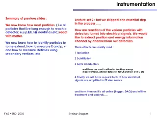
Instrumentation • Lecture set 2 : How are reactions of the various particles with detectors turned into electrical signals. We would like to extract position and energy information channel by channel from our detectors. • Three effects are usually used : • 1 Ionisation • 2 Scintillation • 3 Semi Conductors • and these are used in either for tracking, energy measurements, photon detectors for Cherenkov or TRT, etc • and from then on it is all online (trigger, DAQ) and offline treatment and analysis …. Steinar Stapnes
Ionisation Detectors The different regions : Recombination before collection. Ionisation chamber; collect all primary charge. Flat area. Proportional counter (gain to 106); secondary avalanches need to be quenched. Limited proportionality (secondary avalanches distorts field, more quenching needed). Geiger Muller mode, avalanches all over wire, strong photoemission, breakdown avoided by cutting HV. Steinar Stapnes
Ionisation Detectors Vs(z) x (mm) y (mm) Advanced calculations of electric field, drift, diffusion and signal formation can be done with Garfield. Two dimensional readout can be obtained by; crossed wires, charge division with resistive wires, measurement of timing differences or segmented cathode planes with analogue readout Resolution given by (binary readout) : Analogue readout and charge sharing can improve this significantly when the left/right signal size provide more information about the hit position. From Leo Steinar Stapnes
From CERN-CLAF, O.Ullaland Scintillators Inorganic Crystalline Scintillators The most common inorganic scintillator is sodium iodide activated with a trace amount of thallium [NaI(Tl)], Energy bands in impurity activated crystal http://www.bicron.com. Strong dependence of the light output and the decay time with temperature. Steinar Stapnes
Scintillators External wavelength shifters and light guides are used to aid light collection in complicated geometries; must be insensitive to ionising radiation and Cherenkov light. See examples. From C.Joram Steinar Stapnes
Semi-Conductors Intrinsic silicon will have electron density = hole density; 1.45 1010 cm-3 (from basic semiconductor theory). In the volume above this would correspond to 4.5 108 free charge carriers; compared to around 3.2 104 produces by MIP (Bethe Bloch loss in 300um Si divided by 3.6 eV). Need to decrease number of free carriers; use depletion zone (reduce temperature would also help but one would need to go to cryogenic temperatures) Steinar Stapnes
Semi-Conductors Steinar Stapnes
Semi-Conductors p+ implant Si (n type) n+ implant Silicon Detectors. From CERN-CLAF, O.Ullaland H. Pernegger - CERN G. Bagliesi - INFN Pisa Steinar Stapnes
Semi-Conductors The DELPHI Vertex Detector From CERN-CLAF, O.Ullaland Reconstructed B decays K0 and Lambda reconstruction Steinar Stapnes
Front End electronics Most detectors rely critically on low noise electronics. A typical Front End is shown below : where the detector is represented by the capasitance Cd, bias voltage is applied through Rb, and the signal is coupled to the amplifier though a capasitance Cc. The resistance Rs represent all the resistances in the input path. The preamplifier provides gain and feed a shaper which takes care of the frequency response and limits the duration of the signal. The equivalent circuit for noise analysis includes both current and voltage noise sources labelled in and en respectively. Two important noise sources are the detector leakage current (fluctuating-some times called shot noise) and the electronic noise of the amplifier, both unavoidable and therefore important to control and reduce. The diagram below show the noise sources and their representation in the noise analysis : Steinar Stapnes
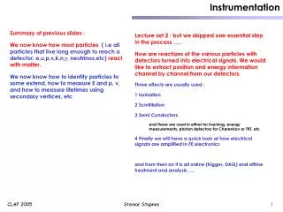
Instrumentation We now know how most particles ( i.e all particles that live long enough to reach a detector; e,u,p,,k,n,, neutrinos,etc) react with matter. We now know how to identify particles to some extend, how to measure E and p, v, and how to measure lifetimes using secondary vertices, etc Essential three detector types are used : 1 Ionisation detectors 2 Scintillators 3 Semi Conductors 4 Finally we have looked briefly at how electrical signals are treated in FE electronics • The detector-types mentioned are either for tracking, energy measurement, photon detectors, etc in various configurations. Steinar Stapnes