Update on ILC Production and Capturing Studies
180 likes | 322 Vues
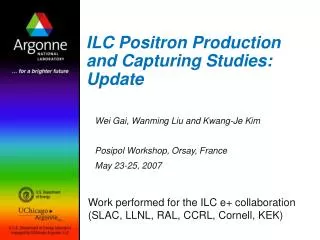
Update on ILC Production and Capturing Studies. Wei Gai, Wanming Liu and Kwang-Je Kim ILC e+ Collaboration Meeting IHEP Beijing Jan 31 – Feb 2, 2007. The ILC e+ system layout. AMD profile and Pre-Accelerator Filed Map Used in the Simulation. AMD field:5T-0.25T in 50cm.

Update on ILC Production and Capturing Studies
E N D
Presentation Transcript
Update on ILC Production and Capturing Studies Wei Gai, Wanming Liu and Kwang-Je Kim ILC e+ Collaboration Meeting IHEP Beijing Jan 31 – Feb 2, 2007
AMD profile and Pre-Accelerator Filed Map Used in the Simulation AMD field:5T-0.25T in 50cm Accelerating gradient in pre-accelerator: 12 MV/m for first 6 m, 10 MV/m for next 6 m and 8.9 MV/m for the rest.
Positron yields from different undulator parameters Target: 1.42cm thick Titanium
Photon Number Spectrum Number of photons per e- per 1m undulator: Old BCD: 2.578 UK1: 1.946; UK2: 1.556; UK3: 1.107 Cornell1: 0.521; Cornell2: 1.2; Cornell3: 0.386
Photon Spectrum and Polarization of ILC baseline undulator Results of photon number spectrum and polarization characteristic of ILC undulator are given here as examples. The parameter of ILC undulator is K=1, lu=1cm and the energy of electron beam is 150GeV. Figure1. Photon Number spectrum and polarization characteristics of ILC undulator up to the 9th harmonic. Only those have energy closed to critical energy of its corresponding harmonics have higher polarization
Photon distribution on target,K=0.92,lu=1.15cm, No collimator Target is 500m away from the end of 100m long undulator. Without collimator, the photon spot size on target is bigger due to high order harmonics
Initial Polarization of Positron beam at Target exit(K=0.92 lu=1.15)
Yield contribution from different harmonics The contribution from harmonics will change with the length of drift between undulator and target. The result showing here is when drift length at ~ 100 m. For longer drift, the contribution from 1st harmonic will increase and contribution from high order harmonics will decrease.
Yield and Pol. The yield will drop from ~1.37 down to ~1.29 when length of drift increased up to 500m from 50m.
Non-immersed/Partially Immersed Target • For cases with non-immersed target, the yield varies with the ramp length d. • For Partially immersed target, the yield also varies with the Bz at z=0. Since the dragging force exerted on target is proportional to Bz^2 on the target, a partially immersed target can lower the power requirement on driving the target while maintaining a reasonable yield. Ramp up from 0 to 7T and has 1st order continuity at the joint point. 5T-0.25T, 50cm ramp length
Normalized Yield as a Function of the Ramp Length Yield is normalized to the yield of immersed case We would like to have the ramp as short as possible to minimize the lost of yield
Normalized Yield as Function of Bz0 for Partially Immersed Target Yield is normalized to the yield of immersed case Ramp length is 2cm for this plot A balance between yield and power consumption in driving the target need to be found.
Current procedure in end to end simulation • Positron production: Using undulator radiation analytical formula to obtain photon distribution(harmonic, energy, polarization,radiation angle); using the obtained photon distribution together with drive e- beam profile and undulator to generate positrons using EGS4 simulation • Beam dynamic simulation: Post processing EGS4 simulation to obtain positron/electron initial distribution(6 dimension phase space); translate the initial distribution into PARMELA particle input; run PARMELA simulation with predefined beamline input. • Post processing all the outputs and calculate yield and polarization.
Disadvantages of current procedure • EGS4 can not do the radiation problem. Either FLUKA or GEANT4 should be involved radiation activation problem. • PARMELA doesn’t have the capability of spin transportation, in order to do spin tracking, one must not only develop his own tracking code but also interface code to glue them together.
Possible solutions • FLUKA + PARMELA + Spin tracking: • FLUKA can do what ever EGS4 does plus radiation activation. Replacing EGS4 is reasonable. • GEANT4: • Can do what ever EGS4 and FLUKA do. • Has spin tracking capability • Can do most of the work PARMELA do • Open source C++ package, can be easily extended. GEANT4 is a program with FLUKA + PARMELA + Spin tracking capabilities.
Particles trajectories image (With 3D magnetic field in AMD EM field in cavity) 1.42cm Ti target AMD cavity Note: Charge Color +1 Blue -1 Red 0 Green