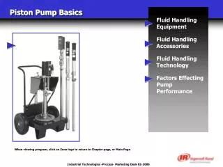
Piston Pump Basics
Piston Pump Basics. Fluid Handling Equipment Fluid Handling Accessories Fluid Handling Technology Factors Effecting Pump Performance. When viewing program, click on Zone logo to return to Chapter page, or Main Page. Fluid Handling Equipment. Pump Design Pump Types Pump Operation

Piston Pump Basics
E N D
Presentation Transcript
Piston Pump Basics Fluid Handling Equipment Fluid Handling Accessories Fluid Handling Technology Factors Effecting Pump Performance When viewing program, click on Zone logo to return to Chapter page, or Main Page
Fluid Handling Equipment Pump Design Pump Types Pump Operation Pump Components Air Motors When viewing program, click on Zone logo to return to Chapter page, or Main Page
Pump Design Inline Pumps Divorced Design Pumps
Inline Pumps • Often used with low viscosity lubricants • Down Tube coupled to Air Motor casting Inline Pumps have a direct connection between the Motor and Lower End
Divorced Design Pumps • Motors and Lower Ends are separate from each other • Tie rods connect Motor to Lower End • Eases Repair Prevents contamination of Air Motor when Lower needs repair
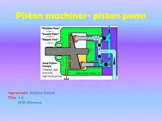
Pump Types Basic Pumps Two-Ball Lower End Pumps Four-Ball Lower End Pumps Chop-Check Lower End Pumps
Basic Pumps • For low-volume delivery of light viscosity fluids • Ratios range from 1:1 to 2:1
Two-Ball Pumps • Lower end contains two ball checks that control fluid flow • Most common type of pump configuration • Used with light to medium viscosity fluids
Four-Ball Pumps • Lower End contains four ball checks that control fluid flow • Used with low viscosity fluids in high flow applications
Chop-Check Pumps • Checks are mechanically pushed onto seats to control fluid flow • Used in extrusion applications with medium to high viscosity fluids Chop-Check pumps are often mounted on rams to transfer fluids
Pump Operation Two-Ball Lower End Pumps Four-Ball Lower End Pumps Chop-Check Lower End Pumps
Two-Ball Lower Operation UpstrokeAs Piston rises, fluid is pulled into pump. Fluid above ball check is lifted out of pump Downstroke The lower ball seats to close off the pump. Fluid is displaced by the plunger, passing through the upper check, to the outlet. Upstroke Downstroke
Four-Ball Lower Operation Upstroke: Fluid passes the lower left ball check into pump. Upper left check is seated. The upper right check rises as fluid exits the pump. The lower right check is forced onto it’s seat. Downstroke: The lower left ball is seated. The upper left ball rises as fluid exits the pump. The upper right check is seated, while fluid is drawn into the pump past the lower right check. Upstroke Downstroke
Chop-Check Lower Operation Upstroke:The lower check rises and the primer plate pulls fluid into the pump. Fluid exits the pump when the upper check seats and rises with the plunger. Downstroke:The lower check seats and the upper check opens. Fluid exits the pump through the upper check. Meanwhile, the primer plate extends into the fluid. It will pull fluid into the pump when the plunger rises. Upstroke Downstroke
Pump Components Packing Assemblies Tube & Plunger Springs Wet Cup
Packing Assemblies • Seal movement of plunger rod • “V” packings for higher viscosity fluids • Cup packings for low viscosity fluids Packings are located in the Body Casting and on the Plunger Rod
Tube-Plunger • The Plunger moves within the Tube • The Plunger transfers fluid from the inlet to the pump’s outlet Typical Plunger Rod (less packings) and Tube
Springs • Compensate for normal wear of the packings caused by pump usage • Wave Springs offer excellent service in hard-duty use • Coil Springs are used to pump lighter viscosity fluids Coil Spring Wave Spring
Wet-Cup • Use of Wet-Sol in Wet-Cup keeps Plunger Rod wetted • This helps prolong packing life Typical Wet-Cup Assembly
Air Motors • Creates reciprocating motion to drive pump • Aro manufactures several styles of Air Motors • 200 Series • “N” Series • 4¼” 6” & 8” • 10” & 12” 10” & 12” Air Motor 4”1/4 - 6” - 8” Air Motor “N” Series Pump 2” & 3”
Air Motor Operation 200 Series Motors “N” Series Motors 4¼” 6” & 8” Motors 10” & 12” Motors
“N” Series Motors Upstroke: Air passes by main piston, through Spool A. This raises both Spool B and main piston. This continues until piston passes upper air port. Downstroke: Air shifts Spool A, exhausting air below main piston and Spool B. “B” shifts, transferring air to top of main piston. Piston will continue downward until passing lower air ports. At that time “A” will shift again, creating upstroke conditions Upstroke Downstroke
4¼”, 6” & 8” Air Motors Upstroke: Air lifts main piston until it contacts pilot rod. Rod lifts valve assembly until air charge shifts valve. Air is now directed to top of main piston Downstroke: Air pushes down main piston until it contacts pilot rod. Rod pulls down valve assembly until air charge shifts valve. Air is now directed to top of main piston Upstroke Downstroke
10” & 12” Air Motors Upstroke: Air flows to large end of valve assembly, shifting valve to the right. Air lifts main piston until it contacts pilot rod. When rod cuts off air to valve, it shifts. Air now passes to top of main piston Downstroke: Air pushes down main piston until it contacts pilot rod. When rod falls, it supplies air to large end of valve. The valve then shifts, directing air to bottom of main piston, creating an upstroke condition Upstroke Downstroke
Fluid Handling Accessories Fluid Regulators Control Handles Follower Plates Mounting Styles When viewing program, click on Zone logo to return to Chapter page, or Main Page
Fluid Regulators • Downstream Regulators are used to control fluid pressure beyond the regulator • Regulators can be used to smooth out pulsation in a pumping system
Control Handles • Used at the final dispensing point • Types of Control Handles include • Flow Guns • Grease Guns • Metered Guns • Extrusion Guns Flow Gun for low viscosity fluids Grease Gun Metered Gun dispenses set quantity of fluid Manual Extrusion Gun for high viscosity fluids
Follower Plates • Used to keep extrusion pump primed • Follower seals drum from air and other contaminants • Follower pushes material toward pump inlet Extrusion Pumps with Follower Plates for 5-gallon or 55-gallon drums
Mounting Styles Wall Mounts Drum Covers Floor Mounts Lifts Rams Cart Mounts
Wall Mounts • Used with light to medium viscosity fluids • Fluid is pumped from drum using a siphon hose Wall mounted pumps located next to fluid containers
Drum Covers • Protect fluid from outside contaminants • Only the pump down tube is submerged • Commonly used with oil or grease pumps Typical oil pump mounted in the bung of a drum cover
Floor Mounts • Used when fluid is stored in a bulk container • Gravity feeds material into pump • Locate pump as close to container as possible Floor mounted Extrusion Pump
Lifts • An internal cylinder lifts the pump from an empty container • Used with medium to high viscosity fluids • Eases change over of empty fluid containers Lift Mounted Extrusion Pump
Rams • Cylinders exert downward force, pushing pump into fluid • Used with medium to high viscosity fluids • Single-Post or Two-Post Rams available Two Post Ram package used with high viscosity fluids
Cart Mounts Allow a pump to be moved to different locations within a work site Pump often uses a siphon hose to draw material from a nearby container Cart-Mounted Pump Package
Fluid Handling Technology Ratio Changing Ratio Fluid Characteristics Packing Types Types of Steel When viewing program, click on Zone logo to return to Chapter page, or Main Page
Ratio The difference in effective size between the air motor piston and the lower end plunger rod Higher ratio pumps produce higher fluid pressures Ratio Calculation: Ratio x Air Inlet Pressure = Fluid Outlet Pressure Comparison of relative Air Motor Piston and Plunger Rod sizes
Changing Ratio Increase Ratio by changing Air Motors Increase Ratio by changing lower ends Swap units within inventory to meet application needs Change Motor: 650483-343650683-343 Lower: 66300-G43 66300-G43 Motor: 4¼” 6” Ratio: 11:1 23:1 Delivery: 4.6-GPM 4.6-GPM Change Lower: 650484-P43650485-P43 Motor: 4¼” 4¼” Lower: 66301-P43 66302-P43 Ratio: 22:1 30:1 Delivery: 2.4-GPM 1.5-GPM
Fluid Characteristics Viscosity Specific Gravity Abrasiveness Corrosiveness
Fluid Characteristics: Viscosity • Viscosity is the measure of fluid’s resistance to flow • Aro measures viscosity in terms of “centipoise.” • Viscosity will determine if a lift or ram is needed Low viscosity fluids flow freely, while high viscosity fluids do not
Fluid Characteristics: Specific Gravity • Specific Gravity is the relationship between the weight of a volume of fluid compared to the same volume of water Fluids with a lower Specific Gravity will float on top of “heavier” fluids
Fluid Characteristics: Abrasiveness • Abrasiveness is the ability of a fluid to wear the surface it contacts • Abrasive fluids can dramatically shorten the life span of a pump lower end Plunger Rod with severe wear caused by pumping abrasive fluids
Fluid Characteristics: Corrosiveness • The ability of a material to chemically react with other materials • The corrosiveness of a material is indicated by it’s pH factor Ball check distorted by corrosion
Packing Types U.H.M.W.-PE (Ultra-High) Teflon® Thiokol Leather Glass-filled Teflon Packings selection is based on fluid compatibility and abrasion resistance
Packing Types: U.H.M.W.-PE • Ultra High Molecular Weight Polyethylene is a good all purpose packing • Common uses are with ink, acids and some solvents • DO NOT use with fluid temperatures over 170°F (77°C) Stack of Ultra-High Molecular Weight Polyethylene packings
Packing Types: Teflon • Chemically compatible with all fluids • Excellent corrosion resistance, but poor abrasion resistance Stack of Teflon packings
Packing Types: Thiokol Leather • Chemically compatible with all fluids • Excellent corrosion resistance, but poor abrasion resistance Complete Spring/Packing Assembly, with Leather and U.H.M.W.-PE “v” packings
Packing Types: Glass-Filled Teflon • Used with acids, solvents and corrosive materials • Used in smaller, 200-series pumps Glass-Filled Teflon Packing used in a 650132-C Pump
Types of Steel Hardened Carbon Steel 304 or 316 Series Stainless 400 Series Stainless 17-4 Series Stainless Tungsten Carbide Steel Treatment
Hardened Carbon Steel • Excellent abrasion resistance • Not suitable for water-borne fluids • Can be hard-chrome plated for longer service-life NM2304A-11 N-Series Pump with Carbon Steel construction