Download
1 / 28
280 likes | 474 Vues
UKNF WP2 The RAL Front End Test Stand. Alan Letchford CCLRC RAL ISIS Injector Group UKNF Meeting 10-January 2007. The FETS team. John Back (Warwick) Aaron Cheng (Imperial) Mike Clarke-Gayther (ISIS) Adeline Daly (ISIS) Dan Faircloth (ISIS) Christoph Gabor (ASTeC) Simon Jolly (Imperial)

E N D
UKNF WP2 The RAL Front End Test Stand Alan Letchford CCLRC RAL ISIS Injector Group UKNF Meeting 10-January 2007
The FETS team John Back (Warwick) Aaron Cheng (Imperial) Mike Clarke-Gayther (ISIS) Adeline Daly (ISIS) Dan Faircloth (ISIS) Christoph Gabor (ASTeC) Simon Jolly (Imperial) Ajit Kurup (Imperial) David Lee (Imperial) Alan Letchford (ISIS) Ciprian Plostinar (ASTeC) Jürgen Pozimski (ASTeC/Imperial) Peter Savage (Imperial)
FETS main components: • High brightness H- ion source. • Magnetic Low Energy Beam Transport (LEBT). • High current, high duty factor Radio Frequency Quadrupole. • Very high speed beam chopper. • Comprehensive diagnostics.
Magnetic LEBT A 3 solenoid magnetic LEBT at 65 keV is being designed at Warwick, based on the one successfully used on the ISIS RFQ pre-injector upgrade. A magnetic LEBT has some disadvantages: increased length and solenoid aberrations can cause emittance growth; uncertainties surround the space charge neutralisation process. However an electrostatic LEBT has been rejected due to the close proximity of the caesiated ion source.
Optimisation of the magnetic design, based on available beam data, is nearing completion.
An initial beam optics design has been completed. Further optimisation will be carried out based on the results of the Mk II pepper-pot measurements. First simulations used an idealised beam of the required emittance based on ISIS LEBT measurements.
Recent simulations have used distributions from the first data analysis of the Mk I pepper-pot results. Beam at LEBT entrance from measurement
Given that the emittance of this beam is at least twice that required for FETS the results are very encouraging.
324 MHz RFQ A 0.5 m, 324 MHz 4-vane RFQ cold model is almost complete. The cold model designed at IC contains all the significant features of the final 4 m long design. Machining operations were tested in Aluminium initially
Machining of the cold model segments was 90% complete. Frustratingly the IC workshop resource became unavailable so machining remained 90% complete. Daresbury laboratory agreed to make the final cuts and machining has started again this week.
A computer controlled bead pull perturbation system is under development at IC to perform cavity field measurements on the cold models
Initial tests have been performed on a pill-box cavity and simple 4-rod RFQ model with good results.
An initial beam dynamics design has been completed at RAL for the FETS 324 MHz RFQ. It showed negligible emittance growth and 94% transmission for an ideal 60 mA beam. Further optimisation is expected.
High speed beam chopper A novel tandem chopper technique has been developed at RAL to overcome the conflicting requirements of fast rise time (< 2ns) and long flat-top (up to 100 s). A ‘fast’ chopper creates a short, clean gap in which a ‘slow’ chopper can switch on. The fast pulser is limited in flat-top but can switch between bunches. The slow pulser cannot switch between pulses but can generate the required flat-top.
A state of the art fast switch developed for RAL has achieved ±1.4 kV with rise and fall times less than 2 ns.
A trimmable helical structure with adjustable delays is being investigated as a replacement for the more ‘typical’ meander line due to higher efficiency. Adjustable L-C trimmer Adjust cable lengths to change delay
Three chopper line optics designs are under investigation. A short line keeps the emittance growth low but makes chopping harder and requires some challenging technology. A long line is ‘easier’ but controlling the emittance is more challenging.
The shortest solution will require novel, compact, high gradient quadrupoles and DTL-like cavities. Hybrid PM and EM quads are being investigated. DTL type cavity CCL type cavity
- - - - - - - Charge separation Photo detachment Detection of distribution I(t,y)-> profile, long. e (TOF) “no” momentum transfer magnetic dipole - - - - - - - - - - - - - - - - - - - I(t,y,x)-> 2 D profile, transv. e Diagnostics Accurate diagnostics are essential for FETS to be successful. In addition to more usual diagnostic devices, non-destructive laser stripping techniques will be employed.
The IAP Frankfurt laser transverse emittance measurement system will be developed further on FETS. Initial investigations have begun at RAL.
2D beam profile measurement through laser tomography is being studied at IC for use on FETS. Electron Collection Laser photo-dissociation
Two orthogonal projections gives the X & Y profiles but coupling information is lost.
Using pairs of mirrors covering 90 sectors allows 2D reconstruction.
A preliminary design of a 4 mirror system has been completed. The first nano-positioning stages and lasers for tests have been purchased.
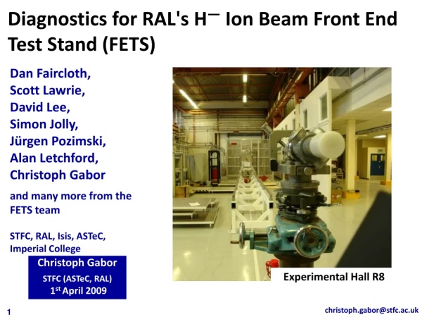
FETS Building R8 at RAL The ground floor of R8 has been taken over for FETS. Refurbishment is almost complete.
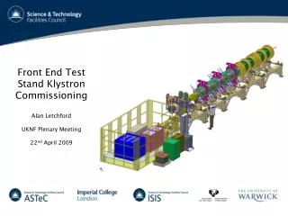
FETS High Power Klystron The Toshiba E3740A 2MW high power pulsed klystron has been delivered to R8. European tender started for klystron PSU.
Next Steps • In 2007 we hope to: • Complete building work in R8. • Install component support structures. • Continue ion source characterisation, install and commission ion source in R8. • Complete LEBT design, procure (and install) LEBT. • Complete the RFQ cold model and test. • Define the high and low power RF systems and RFQ coupling. • Procure klystron PSU and test components. • Characterise PM quadrupoles. • Finalise MEBT design. • Test prototype chopper structures. • Define and order vacuum system. • Commission pepperpot MKII. • Laser tomography and laser emittance tests and finalise designs. • Define control system. • Review radiological aspects and design shielding. • Other stuff …