Download
1 / 18
200 likes | 503 Vues
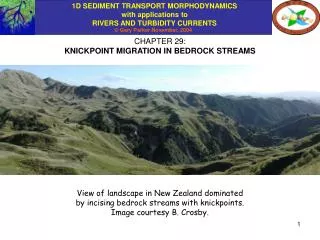
CHAPTER 29: KNICKPOINT MIGRATION IN BEDROCK STREAMS. View of landscape in New Zealand dominated by incising bedrock streams with knickpoints. Image courtesy B. Crosby. WHAT IS A KNICKPOINT?.

E N D
CHAPTER 29: KNICKPOINT MIGRATION IN BEDROCK STREAMS View of landscape in New Zealand dominated by incising bedrock streams with knickpoints. Image courtesy B. Crosby.
WHAT IS A KNICKPOINT? A knickpoint is a point of discontinuity in a river profile. Knickpoints can be manifested in terms of either a discontinuity in bed slope S = - /x or bed elevation . The second kind of discontinuity consists of a waterfall. discontinuity in slope discontinuity in elevation Both types of knickpoints are characteristic of bedrock streams rather than alluvial streams, and both types tend to migrate upstream. This chapter is focused on knickpoints of the first type.
AN EXAMPLE OF A RIVER PROFILE WITH KNICKPOINTS The volcanic uplands of the Hawaiian Islands are dominated by bedrock streams. The top photograph to the left shows the Mana Plain and the region of incised uplands behind it, on the island of Kaua’i. The bottom image to the left shows the location of the Kauhao River on northern edge of the Mana Plain. The long profile of the Kauhao River below shows a clear knickpoint (DeYoung, 2000; see also Chatanantavet and Parker, 2005). adjacent ridges channel bed knickpoint Plot from DeYoung (2000)
WHY ARE KNICKPOINTS CHARACTERISTIC OF BEDROCK STREAMS AND NOT ALLUVIAL STREAMS? Knickpoints in alluvial streams are generally transient features that are not self-preserving. This was shown in Slides 4 and 36 of Chapter 14. An elevation discontinuity in alluvium created by e.g. an earthquake sets up erosion upstream and deposition downstream that causes the knickpoint to dissipate rapidly. This is due to the strongly diffusive component to 1D alluvial morphodynamics discussed in Slide 16 of Chapter 14, which acts to smear out slope differences. One exception to this rule is a gravel-sand transition, where a quasi-steady (arrested) break in slope can be maintained in alluvium, as discussed in Chapter 27. The example to the left is that of the Kinu River, Japan, introduced in Chapter 27.
EXNER EQUATION OF SEDIMENT CONTINUITY FOR A BEDROCK STREAM Since bedrock streams are common (but not confined to) in regions of active tectonic uplift, the uplift rate is include in the formulation. Bedrock is assumed to be exposed on the bed of the river, and the river is assumed to be incising into this bedrock as sediment-laden water flows over it. Denoting the incision rate as vI, the Exner equation of sediment continuity takes the form where denotes a long-term average incision rate (rather an instantaneous incision rate during floods). For many problems of interest involving bedrock the bed porosity p can be approximated as 0.
PHENOMENOLOGICAL RELATION FOR INCISION RATE: m&n’s Until recently most treatments of the morphodynamics of incising bedrock streams have used the following phenomenological relation for the incision rate: where A is the drainage area upstream of the point in question, S = - /x is the slope of the river bed at that point, K is a coefficient and m and n are exponents that may vary (Kirkby, 1971; Howard and Kerby, 1983). The relation make physical sense. Drainage basin A can be thought to be a measurable surrogate for flow discharge. Larger discharge and larger bed slope can both be though to enhance incision. This notwithstanding, the formulation is somewhat dissatisfying, because as long as m and n are free variables, the dimensions of the coefficient K are also free to vary, so defying physical sense. A more physically based, dimensionally homogeneous formulation based on the work of Sklar and Dietrich (1998) is introduced in the next chapter. Meanwhile, m&n’s provides a quick way to gain insight on knickpoint migration in bedrock streams. Stock and Montgomery (1999) provide a compendium of values of K, m and n. A fairly standard pair of choices for m and n is m = 0.5, n = 1.
profile at time t cSDt cDt profile at time t+Dt THE MORPHODYNAMICS OF INCISION ARE CHARACTERIZED BY A LINEAR KINEMATIC WAVE EQUATION Consider as an example the simple choice m = 0 and n = 1 in the incision relation: When substituted into the Exner equation of Slide 5, it is found that This is a 1D (kinematic) wave equation, and c denotes the wave speed of upstream migration. In the absence of uplift ( = 0), the entire bed profile thus migrates upstream so as to preserve form. That is, if i(x) denotes the bed profile at t = 0, the solution to the above equation (with = 0) is
GENERALIZATION TO FULL m&n’s: 1D NONLINEAR WAVE EQUATION The general morphodynamic problem is obtained from the relations of Slides and 6 as follows: where the absolute value ensures incision is always associated with a positive bed slope S = - /x. This relation reduces to a kinematic wave equation in which the speed of upstream migration c varies nonlinearly with bed slope. Now the bed profile deforms as it migrates upstream.
STEADY STATE RIVER PROFILE FOR WHICH INCISION BALANCES UPLIFT The nonlinear kinematic wave equation of the previous page admits the following solution for the steady state case for which the incision rate everywhere perfectly balances the uplift rate : For a constant uplift rate the steady-state long profile of river slope is then given as Various researchers (e.g. Whipple and Tucker, 1999) have used this relation and measured values of S and A to deduce parameters in the incision relation of Slide 6, and in particular the ratio m/n. For the “fairly standard” values m = 0.5, n = 1, the above relation gives Since drainage area A typically increases in the downstream direction, the above relation typically predicts a steady state profile that is upward-concave (with slope S decreasing in the downstream direction.
knickpoint sk(t) h MIGRATION OF KNICKPOINTS CONSISTING OF SLOPE DISCONTINUITIES The focus of this chapter is neither the full morphodynamics of bedrock incision described by the relations of Slide 8, nor the morphodynamics of the steady state. It is rather on knickpoint migration in bedrock streams. A knickpoint consisting of a slope discontinuity is a kind of shock that applied mathematicians call a front. At a front the parameter in question (bed elevation) is continuous, but its derivative (bed slope) is not. Now let sk(t) be the position of the knickpoint, i.e. the moving boundary between the regimes upstream and downstream of it
CONDITION OF ELEVATION CONTINUITY AT THE KNICKPOINT Let u(x, t) denote the bed profile upstream of the knickpoint and d(x, t) denote the profile downstream. The condition of elevation continuity at the knickpoint requires that The migration speed of the knickpoint can be obtained in the same way that the migration speed of a bedrock-alluvial transition was determined in Chapter 16. Taking the derivative of both sides of the equation with respect to t, i.e. results in: where = dsk/dt denotes the migration speed of the knickpoint.
RELATION FOR MIGRATION SPEED OF THE KNICKPOINT Now let Sku be the bed slope just upstream of the knickpoint and Skd be the bed slope just downstream of the knickpoint, so that Reducing the equation at the bottom of the previous slide with the above definitions results in: Further reducing the above relation with the Exner equation of Slide 6 results in the following relation for :
h INTERPRETATION First consider the case Sku > Skd, i.e. a sudden drop in slope in the streamwise direction. This is the case illustrated for the Kauhao River, Kaua’i in Slide 3. As long as vI is an increasing function of S (n > 0 in the incision relation = K AmSn), it follows that (Ak, Sku) > (Ak, Skd), so that and the knickpoint migrates upstream. Next consider the case Sku < Skd. The same reasoning coupled with the assumption the m > 0 also yields and thus the knickpoint again migrates upstream! The implication is that knickpoints in bedrock characterized by slope discontinuities always migrate upstream, at least in the context of the analysis presented here. h
OUTLINE OF A MOVING BOUNDARY FORMULATION FOR INCISION WITH KNICKPOINT MIGRATION Let x = 0 denote the upstream end of the domain, x = sk(t) denote the position of the knickpoint and x = sf denote the downstream end of the calculational domain, a point that is taken as fixed. Introduce the following coordinate transformations. Domain upstream of knickpoint: Domain downstream of knickpoint: Note that goes from 0 to 1 over the upstream reach and goes from 0 to 1 over the downstream reach. The Exner equation is then transformed to the moving boundary coordinates.
COORDINATE TRANSFORMATION FOR THE UPSTREAM REACH Upstream form for Exner:
COORDINATE TRANSFORMATION FOR THE DOWNSTREAM REACH Downstream form for Enxer
SETUP FOR NUMERICAL SOLUTION The two kinematic wave equations and the relation for migration speed are solved subject to a downstream boundary condition and a continuity condition. The downstream boundary condition is one of prescribed variation in base level (i.e. constant base level or base level fall at a prescribed rate), and the continuity condition is one of matching elevations. Thus where base(t) denotes the time variation in downstream base level, the boundary conditions take the form The numerical implementation, which is not given here, follows the outline of Chapter 16 for a bedrock-alluvial transition.
1D SEDIMENT TRANSPORT MORPHODYNAMICS with applications to RIVERS AND TURBIDITY CURRENTS REFERENCES FOR CHAPTER 29 Chatanantavet, P. and Parker, G., 2005, Modeling the bedrock river evolution of western Kaua’i, Hawai’i, by a physically-based incision model based on abrasion, River, Coastal and Estuarine Morphodynamics, Taylor and Francis, London, 99-110. DeYoung, N.V, 2000, Modeling the geomorphic evolution of western Kaua’i, Hawai’i; a study of surface processes in a basaltic terrain, M.S. thesis, Dalhousie University, Nova Scotia, Canada. Kirkby, M.J., 1971, Hillslope process-response models based on the continuity equation, Slopes: Form and Process, Spec. Publication 3, Institute of British Geographers, London, 15-30. Howard, A.D. and Kerby, G., 1983, Channel changes in badlands, Geological Society of America Bulletin, 94(6), 739-752. Stock, J.D., and Montgomery, D.R., 1999, Geologic constraints on bedrock river incision using the stream power law, Journal Geophysical Research, 104, 4983– 4993. Whipple, K.X., and Tucker, G.E., 1999, Dynamics of the stream-power river incision model: Implications for height limits of mountain ranges, landscape response timescales, and research needs, Journal of Geophysical Research, 104, 17,661– 17,674.