Septum Magnets in Beam Transfer Systems
290 likes | 343 Vues
This seminar provides insights into the design and function of septum magnets in beam transfer processes within particle accelerators such as CERN. Learn about the importance of high field homogeneity and low leakage fields in septum magnets. Discover how these devices aid in injecting and extracting particle beams while minimizing losses and ensuring correct trajectories. Gain an understanding of the technical specifications and construction of electromagnetic septum magnets.

Septum Magnets in Beam Transfer Systems
E N D
Presentation Transcript
Beam Transfer Devices: Septa M. Hourican CERN TE/ABT Acknowledgements: B.Balhan, J.Borburgh, M.Barnes, T.Masson, B.Goddard, A. Prost TE-VSC Septa Seminar
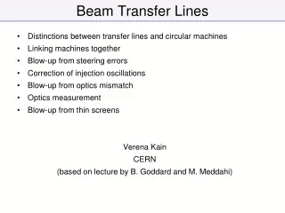
Injection, extraction and transfer CERN Complex • An accelerator stage has limited dynamic range. • Chain of stages needed to reach high energy • Periodic re-filling of storage (collider) rings, like LHC • External experiments, like CNGS Beam transfer (into, out of, and between machines) is necessary. LHC: Large Hadron Collider SPS: Super Proton Synchrotron AD: Antiproton Decelerator ISOLDE: Isotope Separator Online Device PSB: Proton Synchrotron Booster PS: Proton Synchrotron LINAC: LINear Accelerator LEIR: Low Energy Ring CNGS: CERN Neutrino to Gran Sasso TE-VSC Septa Seminar
Region A Field free region Circulating Beam Region B Region with homogeneous field Beam to be deflected Septum What / why is a septum magnet ? a septum (Latin for something that encloses; plural septa) is a wall, dividing a cavity or structure into smaller ones. In the case of septum magnets, the septum separates the high field (injected/ejected beam) region from the low field (circulating beam) region Septa are used to provide the final deflection of beam required to transfer from one machine to another. Normally a kicker magnet deflects (low angle) the beam into the gap of a septum magnet. Main challenges of magnetic septa are a (high) field homogeneity in one region, for deflected beam, and a low leakage field next to the magnet so as not to affect the circulating beam. TE-VSC Septa Seminar
Introduction What do we mean by injection? Inject / Extract a particle beam into/out of a circular accelerator or accumulator ring, at the right time, while • minimizing the beam loss • placing the newly injected / extracted particles onto the correct trajectory with the correct phase-space parameters • Minimum effects on circulating beam A septum magnet can be designed either as an electrostatic device or an electromagnetic device TE-VSC Septa Seminar
I B Current Density very high in Septum Electromagnetic Septum Orbiting beam passes close to the septum in the ‘zero’ field region. Extracted / injected beam passes through the magnet gap (high, homogeneous, field region). Electromagnetic septa are used both under vacuum and outside vacuum, and occasionally without a vacuum chamber (beam passes through air! TE-VSC Septa Seminar
Idealised septum magnet: no play between coil and yoke Leak field virtually 0! Gap field homogeneity near perfect!!! (<10-4) TE-VSC Septa Seminar
Rear Conductor Yoke Septum Conductor x Circulating Beam Extracted Beam B 0 x y z x Direct Drive Pulsed Magnetic Septum (1) Powered with a half sine wave current with a half period time of typically 3 ms. Coil is generally constructed as a single turn, so as to minimize magnet self-inductance. A transformer is used between power supply and magnet to allow use of standard 2kV capacitors. To allow precise matching of the septum position with the circulation beam trajectory, the magnet is also often fitted with a remote displacement system. Often under vacuum to minimize distance between circulating and extracted beam. TE-VSC Septa Seminar
Infrared bake-out lamp Beam “monitor” Septum Beam impedance screen Remote positioning system Direct Drive Pulsed Magnetic Septum (2) Typical technical specifications: • Magnetic length per magnet yoke: 300 - 1200 mm; • Gap height: 18 - 60 mm; • Septum thickness: 3 - 20 mm; • Vacuum (~10-9 mbar); • Laminated steel yoke of 0.35 mm - 1.5 mm thick laminations; • Single turn coil, with water cooling circuits (1 - 80 l/min.); • Bake-able up to 200 °C; • Current: half-sine 7 - 40 kA, half-period ~3 ms; • Power supplied by capacitor discharge; flat top of the current improved with 3rd harmonic circuit and active filters – • A transformer is used between power supply and magnet. PE SMH16 TE-VSC Septa Seminar
Upper half magnet yoke Transport line vacuum chamber Septum Circulating beam vacuum chamber Electrical Connections Rear Conductor y Lower half magnet yoke z x Circulating Beam Cooling PS Bumper 61 & Extractor 61 DC Magnetic Septum Typical technical specifications: • Magnetic length per magnet yoke: 400 - 1200 mm; Laminated steel yoke • Gap height: 25 - 60 mm; • Septum thickness: 6 - 20 mm; • • Multi turn coil, with water cooling circuits (12 - 60 l/min.); • Current range: 1 - 10 kA; • Power consumption: 10 - 100 kW ! The coil and the magnet yoke can be split in two, an upper and a lower part, to allow the magnet to be 'clamped' over the vacuum chamber of the extraction line. LEAR SM12 TE-VSC Septa Seminar
Magnet construction ….A typical electromagnetic septum is only big block of steel with a coil ! Unfortunately for the vacuum group, This block comprises typically 3000 laminated silicon steel plates coated with inorganic insulation often with a total surface area of 300 m2 per magnet ! (450 kg) Then for good measure, we insert extra insulation, kapton sheets, to reduce the possibility of eddy currents, and short circuits, etc In order to achieve UHV compatibility we need a bake out system so we also install a infra red heating array, Operations need to know where the beam is located so we integrate the BI apparatus in the tank also, Operations discover that the beam is not in the right position so they need to move the magnet so we design and integrate a remote operated displacement system, UHV compatible of course ! And as usual there are the associated bellows, gauges, beam impedance screen, sublimators, thermocouples, etc.. TE-VSC Septa Seminar
Thermal / Cooling issues Reduced septum conductor thickness → high current density → high thermal loads → high mechanical stress on the coil Septum magnet ≈ CONTROLLED FUSE The flow characteristics (laminar/turbulent/mixed) in the cooling tube are dependent on the Reynolds number (Re) : Re= interlock system OK ? This magnet needed cooling High Re provides turbulent flow and more efficient heat transfer but also creates cavitation and erosion of the cooling tube Moody friction Factor for the tube Ξ Joule effect heating to be evacuated by cooling I2R = m Cp(T2-T1) to estimate the pressure drop in the cooling circuit. TE-VSC Septa Seminar
Thermal / Cooling issues (2) Typical Coil temperature gradient Significant increases in magnet temperature, including the power connection can lead to load changes as seen by the Power Supply. TE-VSC Septa Seminar
Mechanical forces F on blade: B is the field, I is the current and L is the length, Depending on the geometry, the septum can be treated as a simply supported beam, Where, Max deflection = on mid plane. W is the distributed load, is the length, And the max stress Ex. 2T on the blade of SMV10 at 28 kA Fatigue failure on the mid plane of the septum blade of PSB BISMH Lamination fatigue failure on PE SMH16 TE-VSC Septa Seminar
Remote displacement system Septum LEIR SEH10 20m of SPS septa move together-LSS2 The septum blade has to be positioned precisely in relation to the orbiting beam. Usually implemented are: • radial movement (typically ± 10 mm) • angular movement (typically ± 5 mrad) TE-VSC Septa Seminar
Coil fixation Damping springs have been designed to absorb part of the electromechanical force during the current pulse. Coils are made of Beryllium copper alloy and are inserted at regular intervals along the length of the coil. Various springs in use Stress values The spring is in contact with the septum via a lever which is then clamped in a slot in the magnet yoke. Deformation TE-VSC Septa Seminar
Circulating Beam d Septum Foil V Electrode Extracted Beam E y z x Electrostatic Septum An electrostatic septum is a HV device which utilizes an electric field to deflect the beam. It uses vacuum as an insulator and therefore is critically dependent on UHV for operation. Thin septum foil gives small interaction with beam. Orbiting beam passes through hollow support of septum foil (field free region). Extracted beam passes just on the other side of the septum (high, homogeneous, field region). To allow precise matching of the septum position with the circulation beam trajectory, the magnet is also often fitted with a displacement system, which allows parallel and angular movement with respect to the circulating beam. TE-VSC Septa Seminar
Deflector Foil Tensioners Electrode Beam Screen Foil Electrostatic Septum (PE-SEH23/31) Typical technical specifications: • Septum Molybdenum foil or Tungsten wires; • Electrode made of anodised aluminium, Stainless Steel or titanium for extremely low vacuum applications; • SEH10 LEIR Bake-able up to 300 °C for vacuum in 10-12 mbar range; Typical technical specifications: • Electrode length : 500 - 3000 mm; • Gap width (d) variable: 10 - 35 mm; • Septum thickness: ≤ 100 µm; • Vacuum (10-9 to 10-12 mbar range); • Voltage: up to 300 kV; (10 MV/m) TE-VSC Septa Seminar
Variants septum electrostatic MedAustron Injection septum Cathode inside Anode to allow for both remote displacement systems to be on the same side (free up space on orbiting beam side for other equipment Titanium cathode, molybdenum septum, nominal operating voltage 70 kV but conditioned up to 120 kV W-Re (27%) wire septum Needs ion traps in circulating beam area Very thin septum (60 µm) Very high field in operation possible (>10 MV/m) Low Z seen by the beam TE-VSC Septa Seminar
SEH31 PS extraction LEIR Injection SEH10 Diagonal multi-turn injection in LEIR. Remote displacement at 30º from horizontal plane to allow for longitudinal painting injection scheme. Ti cathode and deflectors to allow for high field strength (Cathode V nom. 70 kV) whilst remaining compatible with XHV (10-12 mbar range). Conditioned at 130 kV Tall cathode, and anode deflector screens to provide required good field region. When HV is present the design of the vacuum vessel and all other components is critical to avoid HV breakdowns Cathodes and deflectors undergo special surface treatment, polished, cleaned, chromic and sulphuric anodizing, Conditioning of HV components is necessary TE-VSC Septa Seminar
Vacuum Considerations To reduce septum thickness as seen by the beam (apparent septum thickness), complex, thin walled vacuum chambers can be used, on which septum magnet can be clamped To achieve XHV the chamber is NEG coated- complicated (difficult to manufacture) and UHV compatible (material quality) vacuum chambers are often required for injection/extraction points. Circulating Beam Ejected Beam TE-VSC Septa Seminar
Vacuum Considerations To reduce apparent septum thickness even further, magnet can be put under vacuum thus eliminating the vacuum chamber in the gap. To reach UHV, pumping is required and baking may be necessary which requires all the relevant heating equipment. In this case quartz lamps, heating jackets, reflectors, ceramic insulators Material choices are critical Radiation resistant, high voltage/current compatible, temperature, vacuum compatible, halogen free, mechanically suitable for strength, In some cases, such as LEIR, where pressure is critical NEG coating may have to be applied to the chambers which require activation systems. This involves custom designed surface treatment vessels TE-VSC Septa Seminar
Vacuum considerations Bake out For the septa under vacuum it is necessary to perform bake outs up to 300 C Bake out is achieved in several ways, Bake out lamps- Quartz lamps controlled by thermocouples NEG elements used as heating elements Standard or customised bake out jackets for tanks and pumps Rates of temperature increase controlled at approx. 10 C per hour Bake out cycles established with TE/VSC but normally last for 5 days 1 day to reach temperature 1-2 days flat top and 2-3 days for cool down to 50 C TE-VSC Septa Seminar
Diagnostics and typical modes of failure Material failure damping spring Damaged kapton insulation provokes arc Loose coil connection Magnet failures usually have an influence on vacuum - slow / fast pressure rises Current signal can be adversely affected – electrical shorts, earthing problems, O/L, Beam trajectory can be affected, overheating on dc magnets – thermal switches, water temp. monitoring, Material failure (fatigue) Braze failure on cooling tubes TE-VSC Septa Seminar
Coil Yoke Eddy Current Septum I I Orbiting Beam Gap • Septum y z x Eddy Current Magnetic Septum Powered with a half or full sine wave current with a period of typically 50 μs. Coil is generally constructed as a single turn The coil sits around the back leg of the C shaped yoke, coil dimensions are generally not critical. When the magnet is pulsed, the magnetic field induces eddy currents in the septum, counteracting the fringe field created. The septum can be made very thin, but water circuits may be needed at the edges to cool the septum. To reduce further the fringe field of the eddy current septum a copper box (return box) can be placed around the septum magnet. Also a magnetic screen can be added next to the septum conductor. These modifications permit the fringe field to be reduced to below 1/1000 of the gap field at all times and places. TE-VSC Septa Seminar
BS1 Prototype Eddy Current Septum Septum Eddy Current Magnetic Septum (3) Typical technical specifications: • Magnetic length per magnet yoke: 400 - 800 mm; • Gap height: 10 - 30 mm; • Septum thickness: 1 - 3 mm; • Vacuum (~10-9 mbar), or out of vacuum; • Steel yoke with 0.1 - 0.35 mm thick laminations; • Single turn coil, with water cooling circuits (1 - 10 l/min.); • Current: ~10 kA; • Fast pulsed : 50 μs; • Powered with a capacitor discharge; half-sine or full sine-wave. TE-VSC Septa Seminar
Steel yoke Coil Steel to avoid saturation I x • Circulating Beam Thin Septum I Aperture Lambertson Septum (principle) • Current: DC or pulsed; • Conductors are enclosed in steel yoke, “well away” from beam; • Thin steel yoke between Aperture and circulating beam – however extra steel required to avoid saturation; • Septum, as shown, difficult to align. • Extraction Septum shown: • Use kicker to deflect beam horizontally into aperture; • Lambertson deflects beam vertically (orthogonal to kicker deflection). TE-VSC Septa Seminar
Beam Injected into LHC Counter-rotating LHC Beam Transfer line from SPS LHC Injection – Lambertson Septum • Septum deflects beam horizontally to the right; • Kicker deflects beam vertically onto central orbit. • Note: To minimize field in LHC beam-pipes, additional screen is used. TE-VSC Septa Seminar
Other types of septum magnets • • Massless septum More recent developments include massless septa: no physical separation between the field free region and homogeneous field region. • complex magnetic circuit • additional coils close to septum area, distributed coils around field free region to cancel a dipole leak field • Apparent septum thickness rather big (> half the gap height) • Requires careful design and collimation of particles deflected by septum field I • Opposite fields in adjacent gaps yield ZERO mechanical forces on septum • Cooling remains critical • Orbiting beam gap needs very high field homogeneity • Additional dipole magnets required to complete injection or extraction process Opposite field septum TE-VSC Septa Seminar
Principal Parameters for Magnetic Septa in the CERN Complex Thanks for your attention, TE-VSC Septa Seminar