SPS configuration and beam transfer
450 likes | 626 Vues
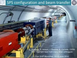
SPS configuration and beam transfer. B. Goddard, G. Arduini , J. Bauche , K. Cornelis , CERN With important input from many other colleagues First SHiP Workshop, 10-12 June 2014. Outline. SPS configuration Layout and fixed target zones Beam parameters for SHiP Protons per year

SPS configuration and beam transfer
E N D
Presentation Transcript
SPS configuration and beam transfer B. Goddard, G. Arduini, J. Bauche, K. Cornelis, CERN With important input from many other colleagues First SHiP Workshop, 10-12 June 2014
Outline • SPS configuration • Layout and fixed target zones • Beam parameters for SHiP • Protons per year • Slow extraction and potential issues • Beam transfer to target • TT20 reuse • Switching into the new SHiP beamline • Dilution system • Schedule • Summary and outlook
SPS Fixed-Target facilities North Area Commissioned 17 June 1976 and still going strong CNGS/AWAKE HiRadMat Now: LHC injector, beams to North Area, HiRadMat, AWAKE Plasma wakefield facility
Beam parameters for SHiP • Baseline based on past peak SPS performance (for integrated performance estimate we assumed 4.2x10¹³ p/cycle on target). • Slow extraction for 1 s – possible implications later… • Ultimatescenario basedon the target to accelerate up to 7x10¹³ p/cycle beingstudied(LAGUNA-LBNO) for the moment (very) hypothetical. • Cannot count on « ultimate » parameters • Should not over-constrain (or kill) good design options for « ultimate »
Integrated performance - input • Constraints considered: • Concurrent operation with LHC, Fixed Target program for NA TCC2 targets, Machine Development • Maximum resistive power that can be dissipated in the SPS main magnets (39.0 MW limited by cooling) • Based on recent performance and on 2011 injector schedule
Integrated performance - estimate Baseline parameters Realistically somewhere around here? 4e19 p+/y for ship means about 5e19 p+/y extracted (factor 2 aboveprevious “record” year from slow extracted beam through LSS2)
Summary of p.o.t. analysis • The goals integrated performance of 4x10¹⁹ p.o.t./year is within reach for the beam parameters considered and with realistic assumptions on: • time-sharing with other programs • machine availability • transmission efficiency • Potential issues: • Requirements form TCC2 experiments in terms of p.o.t. • Performance of electrostatic septa studies • Radiation levels in North Extraction (LSS2) area studies
Slow extraction and losses Stable area in H phase space defined with 6-poles Shrink area by approaching tune to 1/3 integer Particles follow separatrices out across septum wire Spiral step at (60 um) wire ~15 mm determines losses • Transverse losses typically 0.5 – 1.0 % • Sparking of ZS septa and damage to wires is possible • Spill of 0.1 – 10 sec possible
ZS septa Anodes made of 2080x 60 um W/Re wires 5 individual anodes, aligned together over ~20 m
Slow extraction (vs fast) • For machine, fast extraction is conceptually better • Local (and distributed) losses are a factor of ~10-100 lower • Machine protection is well-known and controlled • Can extract all the intensity SPS can accelerate • Can easily follow any upgrade in SPS intensity • 20 us spill length • Cannot do fast and slow to NA in same SC • (Also needs new Non Local Extraction to be commissioned) • Slow extraction: may well limit performance • Beam losses in LSS2, which activate equipment beyond tolerable levels (see talk by Heinz Vincke for more details on RP concerns) • Septumsparking and damage • Radiation damage to cables and other components • Mitigation would be fewer p+/cycle, or (maybe better) longer cycles • But operational now, and no issues with multi-cycling with NA
Slow extraction spill • Spill in p+/s moderated by servo quadrupoles, which work in feed-forward to correct mains harmonics • Needs regular adjustment (daily) for good correction • With 1 s extraction, additional overshoot at start of spill likely Well-adjusted p+ spill Less well-adjusted p+ spill - Experiments should certainly design for spikes in p+ rate of 2-3 times average - Also a concern for target, for any large initial overshoot
Other extraction options? • Topics for future study – but no magic bullet
Beam transport to top of TT20 • TT20 presently operating with slow-extracted 400 GeV/c beams, so no major functionality changes • Probably need improvements to loss monitoring • Some minor changes of instrumentation near switch region • Optics would need some modifications near splitters • Already done* for 100 GeV transport for short-baseline studies, no major problems found • Need to check implementation feasibility of ‘fast’ settings changes for TT20 between FT and SHiP beams (magnets should be OK as laminated – to check convertors, interlocking) *M.Kowalska
Switching from TT20 at 400 GeV • Already studied in a lot of detail for LAGUNA-LBNO • Difficult with 1336 Tm rigidity primary beam! • Recent idea to switch at splitter magnets MSSB.2117 • Replace existing magnet with bipolar laminated Lamberson septum splitter with larger H aperture in high-field region • No show-stoppers identified to date for preliminary considerations
New switch/splitter magnet • Need to provide opposite-polarity dipole field for SHIP cycles, with larger horizontal aperture, while keeping existing MSSB functionality for FT cycles • New magnet functional specification • High radiation resistance (~50 mSv/h activation typical) • Very high reliability design • 0.8 T dipole field, 4.7 m magnetic length, 5.2 physical • Laminated yoke (now solid iron) • Min ramp up/down time ~2 sec • Same aperture and septum dimensions as present
Existing MSSB • Present magnet – very effective design with separate vacuum envelope, special mineral insulated evacuated cable, precision machined septum insert • Need to increase gap width from 400 to 530 mm and build laminated yoke Existing New?
Comments on magnet feasibility (MSC/EPC/ABT) • Present MSSB design is in-vacuum Lambertson, clever vacuum separation for coils in air, radiation robust materials and assembly • 0.8 T in gap means 1.6-1.8 T at point of septum – not possible to increase. 0.8 T limit for new design • Need about 60 kA – turns. • Laminated yoke essential – existing SPS septum technology. Stacking factor can be 98%, so magnet length might increase 2%, to maybe 4.8 m. • “Such a laminated magnet should be feasible – but will be expensive” • Powering feasible, using Linac4 converter technology • Power converter location to be defined (new building) – “BA80 full”
Elements downstream of switch • Can be something which looks symmetrical to T6 line, but on other side of T2/T4 beamline Splitter/switch First quad possible SHIP beamline
Other beamline elements • Need several (~10) main dipoles as early as possible in line to move beam out of TDC2 • First iteration, assume 9x MBB dipoles (SPS main dipoles) which give about 8 mrad at 1.8 T • Detailed integration needed, depends on available magnets • Total inventory ~20 main magnets, ~10 correctors/smaller magnets, with ~20 new power converters
First ‘realistic’ geometry T2 SHIP line Lattice files for CE for first layouts of tunnels and caverns (see John Osborne’s talk)
Beam transport to target • ‘Easy’ problem as need dilution – drift alone is good! • Some first basic checks indicate 2/3 km beta functions possible in H/V planes, giving ~6 mm beam spot sigma
Dilution – optimisation? • Beam density (p+/mm2) on target an issue • Can try and optimise sweep to spread beam out over as much of the target as possible • For LHC we reliably sweep 350 MJ in 86 us, with rigid 7 TeV beam and 150 mm radius… …must be able to do better than a simple circle for SHiP! LHC beam dump sweep See later talk by Marco Calviani
Archimedean spiral sweep? • R = q^n • Equal separation between adjacent spirals. • Test sweep: adjusted frequency as a function of radius to also give equal spacing in unit time along sweep length • Radius 5-35 mm, total path 620 mm (cf 190)
Dilution magnets and powering • Need about 0.2 mrad peak kick per plane • 150 m drift between sweep magnet and target • Assume MPLH type (SPS extraction bumper) • Max 400 A in 300 ms, for 1.2 mrad kick • 1200 A/s means ~3 Hz sine is possible for 0.2 mrad • Here f0 changes from 2.8 Hz at 0.23 mrad, to 20 Hz at 0.03 mrad. So dI/dt and V should just about be feasible
Schedule considerations (beamline) • First estimates made on basis of: • detailed planning made for other recent studies; • Experience with HiRadMat construction; • Experience with CNGS construction; • Discussions with magnet group on new MSSB VERY PRELIMINARY!
TT20/new beamline junction – LS2 • LS2 = LHC Long Shutdown2 (18 months from mid 2018) • Remove TT20 elements to remove over ~150 m before start of junction cavern civil engineering works. Special procedures with radioactive equipment. 1 month • [Civil engineering work] • Reinstall services and cabling: 4 months • Resinstall and test TT20 beamline elements: 2 months (1 month in parallel with services) • Total time where CE/beam excluded : 6months • Not to neglect: cooldown time before dismantling! CRITICAL
Conclusions and outlook • SPS has potential to deliver 4e19 p.o.t. annually for SHiP with 1e19 p.o.t. for other NA experiments • Will be difficult to improve on this • A 1 s slow extraction in LSS2 is feasible but may limit performance: losses, septum performance, radiation damage • 4.5e13 p+/cycle is ambitious with 1 s flat top • 5e19 p+/y extracted (including NA beams) will be twice record • Beam transport through TT20 looks straightforward • New switch/splitter to keep compatibility with NA is “feasible” • Dilution system may be optimised to ease target constraints • Planning of LS2 work critical for overall schedule • Detailed technical studies on critical items, with more accurate costing and scheduling will be next steps • Start machine studies of extraction limits and losses (2015?)
Integrated performance: Ultimate (hypothetical) Actual gain in p.o.t. for SHiP is ~30%, for 55% increase p+/spill…
Extraction options from LSS2 • Fast extraction best for machine • But spill length very short…. • ….no kickers in LSS2 (nor space for them) • …and not compatible with NA FT beam supercycle (as yet) • Resonant best for experiment, but concerns about performance reach • Losses, activation, septum damage • Upgrade potential (to make use of any future SPS improvement)
WANF – ½ integer resonance - Total of ~7.2e19 p+ in 5 year, but specific losses 3x that for 1/3 integer slow extraction - Activation levels can be taken as similar to those expected for LSS2 with SHiP
Past performance for FT beams • Slow extraction to NA targets • Recent max (2007) about 2.3e19 p+/y • Typically 1e19 –2014 target is 2.4e19…
CNGS: 1.8e20 p+ 2006-12 From CNGS Project web
Past performance for CNGS beams • Maximum in “recent” years about 5e19 p+/y • Fast extraction to CNGS target (loss “free”) • Limit: CT losses at PS extraction septum – no MTE CNGS 2011
Fast extraction • Very low transverse losses (total ~e-4 for CNGS, dominated by longitudinal) • Machine protection needs to be good – no damage for CNGS or LHC in 5 years • Drawback for target and experiment: 1x 20 us or 2x 10 us spill time…
LSS2 fast extraction for SHiP • No extraction kickers in LSS2 • Non-local extraction NLE tested in 2010 at 440 GeV, using kickers in LSS6 to extract in LSS2 • Not yet near being operational
Exotic extraction ideas • Fast-burst Multi-Turn Resonant Extraction (MTE)* • Repeated trapping of small part of beam intensity in resonant islands, followed by fast extraction • Could maybe foresee to extract full beam in 20-50 mini-spills of 100 us long (4 SPS turns) • Total spill time is then about 2-5 ms • Could have 20-50 ms between mini-spills, to keep this within 1 s flat-top • Is this range of any interest for experiments and target? • Totally untested idea • Major new HW needed: 2 sets of “MKE like” 400 GeV kickers for closed bump -> cost, impedance, space in lattice *proposed by M.Giavannozzi
ZS septa 5x 3m long septa, 220 kV
ZS septa 220 kV, 2 cm HV gap
Comments on (vertical) geometry • Presently kept SHIP line at same level as top of TT20/TDC2/TCC2 • possible to easily tilt beamline up or down by 10 – 15 mrad – is this required (RP, CE)? SHIP line