Download
1 / 20
200 likes | 301 Vues
PS-to-SPS Transfer Studies. Helga Timkó BE-RF-BR in collaboration with Theodoros Argyropoulos , Thomas Bohl, Heiko Damerau , Steven Hancock, Juan Esteban Müller, Elena Shaposhnikova. Outline. Reminder of previous results Measurements Simulations in BSM

E N D
PS-to-SPS Transfer Studies Helga Timkó BE-RF-BR in collaborationwith Theodoros Argyropoulos, Thomas Bohl, Heiko Damerau, Steven Hancock, Juan Esteban Müller, Elena Shaposhnikova
Outline • Reminder of previous results • Measurements • Simulations in BSM • Optimisation of PS bunch rotation • Voltages and timings • Phase and energy errors at injection • Their impact on the transmission • SPS voltage at injection • Losses at the start of the acceleration ramp SPSU-BD Meeting
PS-TO-SPS TRANSFER: PREVIOUS RESULTS
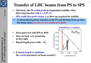
MDs: 25 ns and 50 ns beam • 50 ns: 4th July 2011 • 25 ns: 7th November 2011 • Transmission didn’t improve using 900 kV
PS rotation timing • However, in the MDs above we adjusted only t80 MHz • t40 MHz = 150 μs was kept the same for both 600 kV and 900 kV cases SPSU-BD Meeting
Corresponding simulations • Corrected: now with SPS 800 MHz component in BSM • Reproduce exp. results when emittance blow-up is added SPSU-BD Meeting
Emittance blow-up • … turns out to be justified (MD on 1st November 2011): • There is an emittance blow-up in the PS at FT SPSU-BD Meeting
Bunch shapes • … look difficult to capture: what can we do about these long tails? SPSU-BD Meeting
PS-TO-SPS TRANSFER: OPTIMISATION STUDIES
Optimising the bunch rotation • For 1+2 cavities, optimal timing reduces losses: 4.4 % 3.5 % • Using 2+3 cavities instead of 1+2: 3.5 % 1.3 % SPSU-BD Meeting
Optimising the bunch rotation • For 1+2 cavities, optimal timing reduces losses: 4.4 % 3.5 % • Using 2+3 cavities instead of 1+2: 3.5 % 1.3 % • Transmission is better in BLM, but BLM is unstable SPSU-BD Meeting
Optimised bunch shapes … now improved: tails less populated SPSU-BD Meeting
Effect on transmission • With optimised timing and 900 kV in the PS: • Losses are reduced, despite having longer bunches SPSU-BD Meeting
PS-TO-SPS TRANSFER: FURTHER PARAMETERS OF IMPACT
Injection to SPS: phase and energy errors • When the timing t40 MHz is 30 μs belowoptimal SPSU-BD Meeting
Injection to SPS: phase and energy errors • When the timing t40 MHz is optimal SPSU-BD Meeting
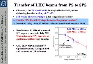
SPS capture voltage • The choice of the SPS voltage at injection can largelyinfluence the losses in the beginning of the acceleration ramp • Observed ranking in measurements: • The best: 2 MV at injection, 3 MV in-between injections (23 MV) • 2 MV constant and 3 MV constant result in more losses • Losses vary with beam intensity, emittance 800 MHz RF voltage, number of injected batches, etc. SPSU-BD Meeting
SPS capture voltage • Using the real voltage and momentum programme for the acceleration ramp, we simulated injection + acceleration: • 23 MV has 3-4 % better transmission than 3 MV • No difference between 2 MV and 23 MV is seen in our sims SPSU-BD Meeting
SPS capture voltage: interpretation of results • Constant injection voltage the bunch fills the bucket • Higher voltage more losses during acceleration • 23 MV behaves as 2 MV constant – at least in our simulations, where intensity effects were not considered: SPSU-BD Meeting
Summary • Even after optimisation, the PS “S” bunch completely fills the SPS bucket sensitive to settings and intensity effects • Simulations predict: bunch shape at transfer can be considerably optimised by PS rotation voltages and timing • Use of 3rd 80 MHz cavity gives ~ 2 % improvement in transmission • Use of 3rd 40 MHz cavity gives smaller improvement, ~ 1 % • New optimum timings for both present configuration and additional cavities to be tested in MDs (planned 2012) • Injection errors in phase and energy add ~ 1 % losses • BSM increases losses by ~ 1 % compared to single RF • SPS capture voltage can affect losses in the beginning of the acceleration ramp • Simulations explain empirically found improvements for 23 MV • We can expect significant increase in losses for higher emittances (intensities) All simulations so far were done for single bunches, without taking intensity effects into account. SPSU-BD Meeting