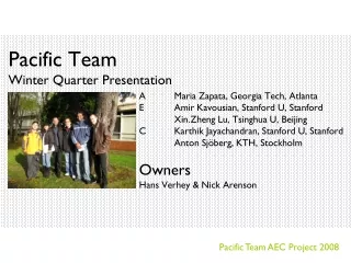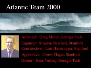
Pacific Team 2000
Pacific Team 2000. The Project. Year 2010 Oregon Coast Rebuild 3-story Classroom & Lab Facility Pacific University Engineering School. Project Requirements. A “showcase” building 30 ft. height limitation Maintain existing footprint $5,500,000 budget (yr. 2010 $)

Pacific Team 2000
E N D
Presentation Transcript
The Project • Year 2010 • Oregon Coast • Rebuild 3-story Classroom & Lab Facility • Pacific University Engineering School
Project Requirements • A “showcase” building • 30 ft. height limitation • Maintain existing footprint • $5,500,000 budget (yr. 2010 $) • One year construction duration
Architectural Requirements • Consider: • Occupancy needs, security needs, privacy needs, acoustic needs, day lighting needs, and views • Emphasize: • Circulation, light, orientation, views, scale of space, connection of functional spaces, quality of the relationship of inside and outside, color, texture, visual language of the elements
Winter Quarter Alternatives:alt 1 Previous design
Winter Quarter Alternatives:alt 1 Engineering & Construction • Explored Structural Systems • Steel • Concrete • Preferred Structural System • Steel EBFs w/composite deck • Construction Cost • $3.8 Million
Winter Quarter Alternatives:alt 2 Sun Pattern Redesign Conceptual goal to use a predefined circulation pattern and bring it into the building; structural elements exposed to capture sun shadows
Winter Quarter Alternatives:alt 2 Engineering & Construction • Explored Structural Systems • Steel • Concrete • Preferred Structural System • Exposed steel EBFs w/composite deck • Construction Cost • $4.2 Million
Winter Quarter Alternatives:alt 3 Puzzle Concept Conceptual goal to create a building that speaks to connections between disciplines within Each puzzle piece works as a functional block, symbolically representing with three materials, three disciplines
Winter Quarter Alternatives:alt 3 Engineering & Construction • Explored Structural Systems • Steel • Concrete • Preferred Structural System • Steel SMRFs w/composite deck • Construction Cost • $4.0 Million
Winter Quarter Alternatives:alt 4 Structural Engineering Design • Reverse order of roles in design process; engineer to work first with intriguing structural system, architect to layout rooms and advise
Winter Quarter Alternatives:alt 4 Engineering & Construction • Explored Structural Systems • Steel • Preferred Structural System • Steel EBFs and cables w/composite deck • Construction Cost • $4.6 Million
Decision Matrix – A/E/C PROS CONS Dynamic, radial, curvilinear, sun pattern Semi-regular bays sizes and layout Easier to construct (regular layout, little welding) Most flexible puzzle piece parti material-functional block relationships Braced frames have dual purpose of “backing” cantilevers & lateral load support Most dynamic interior spaces (auditorium), sunpatterns, shadowplay Structure integrated with architecture Extremely interesting structural system Regular structural patterns – many common components throughout • Costly atrium space • Vibration problems • May not challenge engineer • Long cantilevers • No economies of scale • Circulation undeveloped • Very irregular layout - large number of angled connections • Expensive to construct • No relationship to site or context, lack of spatial variation creating architectural limitations • Deep piles require lots of time & money, large overhanging portion 1 2 3 4
End of Winter Quarter Reevaluation of Architects Role in Design Process: • How can the structural system meet height/program requirements? • How can the structural system set up by engineer create/provide meaning for the users of the space? • How can the structural system provide a form that upholds this meaning? • And how can design uphold a “high tech” feel desired by team and client?
Richard Rogers Searching for precedent: What other buildings have used cables? • Richard Rogers buildings use cables to “pull” up a form for unhindered space • beneath How can a cable system create its own form?
Santiago Calatrava How can cable stay structure inspire form?
Goal : to create an exterior relationship with nature while still maintaining an interior “high-tech” feel with a cable stay system
Iteration 2: Accommodating program Auditorium Main building block Large classrooms
Iteration 2 Plans Floor1 Floor3 Floor2
Iteration 3 Grids discussed with structural engineer
Iteration 4: changing layout of cantilever forms Original layout New layout
First Cantilever Proposed by Architect • Architect: • Proposes cable-stayed system with ground anchors • Engineer: • Small rise creates large cable forces & overturning moments • Construction Manager: • Size of required foundations creates concerns
Second Option: More Cables • Architect: • Structures do not relate to interior activities • Engineer: • Compromise between aesthetics & structural functionality sought
Third Option: The Propped Cantilever • Architect: • How can volume be maintained and have a feasible structure? • Engineer: • Depth needed for king-post truss interferes with interior • Construction Manager: • Good constructability, capabilities for prefab
Fourth Option: Cables w/ Buttress Wall • Architect: • Reintroduced cable stayed system • Engineer: • Earthquake forces require large number of cables • Construction Manager: • Concern over constructability expressed
Final Option: Steel Truss Cantilever • Architect: • Volume maintained and enhanced through truss system • Engineer: • Provides for a very efficient and clean system • Construction Manager: • Steel truss w/prefab risers minimizes construction time
Circulation: Floor 1 Floor 2 Floor 3
Specifications: For fireproofing exposed interior structure: intumescent paints • 100% asbestos-free; thin film; lightweight • Factory formulated; no onsite mixing • Aesthetically pleasing, architectural finish • 3 1/2 hour fire protection
Specifications: Under floor mechanical system • Benefits of under floor air distribution system: • significantly reduced energy costs • downsizing of conventional plant equipment • reduced cooling-energy requirements when compared withconventional HVAC systems
~5o Shift Structural Design Goals • At first.... • To reflect the main axis shift of the architecture in the structure • To incorporate the cable-stayed concept from Alternative #4
Structural Design Goals • After cost & time issues were considered.... • To use a simple, shop fabricated system for the 60 ft. cantilevers • To use an orthogonal grid for the main block of the building and to expose the structure where necessary