RPR Interconnection Topologies: A Comparative Analysis
100 likes | 195 Vues
Explore two basic RPR interconnection topologies (A and B) and their applications. Learn when to choose each based on network deployment flexibility and cost considerations. Illustrative slides provided.

RPR Interconnection Topologies: A Comparative Analysis
E N D
Presentation Transcript
RPR Interconnection Topologies zhaisuping@huawei.com yanw@huawei.com IEEE802.17 WG Orlando, Florida USA March 11~16, 2007
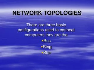
Two Basic RPR Interconnection Topologies Topology A Topology B
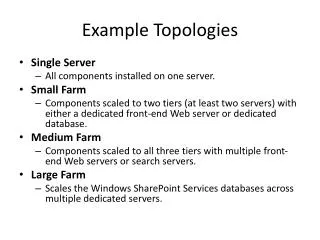
The Comparison of Two Topologies – Cont. Tentative Conclusion (need further discussion): When the requirement of network deployment flexibility outweighs the cost, then the Topology B is used, or else the Topology A is recommended in the RPR interconnection rings network.
The following slides will illustrate the different application scenarios for the interconnected RPR rings. The following figures take the Topology A as example, but the same topologies also apply to Topology B as well.
Application Scenario 1 • There are several subtending rings across one ring. • Each pair of interconnected stations ({A, B} and {C,D}) are independent and belong to different protection groups.
Application Scenario 2 • There are several subtending rings across one ring, and these subtending rings share a common station. • Each pair of interconnected stations ({A, B} and {B, C}) are independent and belong to different protection groups.
Application Scenario 3 • There are several subtending rings across one ring, and these subtending rings share the same interconnection stations. • For the usual deployment, subtending access rings are not communicated each other, they only need to communicate with the aggregation rings. • But if the subtending access rings need to communicate each other, they still can at the cost of some implementation complexity.
Application Scenario 4 • We don’t want support this disordered topologies. Do we want?