Download

1 / 22
230 likes | 490 Vues
RF scheme of electron linear accelerator with energy 200-500 MeV. Levichev A.E Budker Institute of Nuclear Physics SB RAS. Introduction. Debuncher-monohramator. Accelerating structure. Accelerating structure .

E N D
RF scheme of electron linear accelerator with energy 200-500 MeV Levichev A.E Budker Institute of Nuclear Physics SB RAS
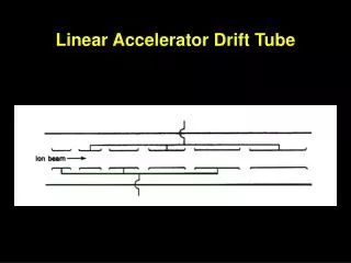
Accelerating structure Accelerating structure. 1 – Regular cell, 2 – Wave type transformer, 3 – Connection cell, 4 – Connection diaphragm, 5 – Structure frame with cooling system.
Accelerating structure BINP produced accelerating structure. Accelerating cells and wave type transformers.
RF power source Basic parameters of TH 2128 C/D klystron. Picture of TH 2100 klystrons series.
Modulator Parameters of К2 modulator series (ScandiNova Systems) Modulator К2-3
Power compression system BINP made SLED type power compression system Main parameters of BINP made power compression system.
Measured input and reflected power from SLED system cavities
Bunching system 1 – two sub harmonic cavities, 2-bunching cavity with main frequency, 3 – parallel coupled accelerating structure Electric field distribution along accelerating cavities
Prototype of parallel coupled accelerating structure The klystron feeds the cavity 1 based on rectangular waveguide and it excites the accelerating cavities 2. The connection between exciting and accelerating cavities is performed by magnetic field with help of slots 3. The copper reactive posts 4 are needed to tune the frequency of the exciting cavity. The magnetic system based on the solenoids or permanent magnets can be placed in the port 5. Scheme of parallel coupled accelerating structure Prototype of parallel coupled accelerating structure with electron beam energy of 4 MeV and frequency of 2450 MHz
Results of beam dynamics calculation in the bunchig system: L(z) – beam length, Wav(z) – average beam energy
Initial and final beam parameters in the bunching system • Beam parameters in the end of bunching system are following: • beam capture is 100% • average beam energy is 6.1 MeV • normalized transverse and longitudinal beam emittances are 55 mm∙mrad • r.m.s. energy spread is 0.25 MeV • beam radius less then 5 mm • equivalent beam with normal distribution will haveσz=1.7 mm • Initial beam parameters are following: • energy is 200 keV, • particles number is 2×10¹⁰, • current length is 2 ns, • beam radius is 5 mm, • uniform longitudinal and transverse beam distribution Longitudinal distribution for 100% of particles in the end of bunching system: 1 – result of beam dynamics calculation, 2 – equivalent normal distribution with σz=1.7 mm
Beam dynamics in the main linac Longitudinal distribution for 100% of particles in the end of the second accelerating structure with bunching and without preaccelerating : 1 – result of beam dynamics calculation, 2 – equivalent normal distribution withσz=1.0 mm. Longitudinal distribution for 100% of particles in the end of accelerator with bunching and preaccelerating: 1 – result of beam dynamics calculation, 2 – equivalent normal distribution withσz=1.7 mm
Beam dynamics in the main linac Beam energy spread in the end of the second accelerating structure with bunching and without preaccelerating. In compare with preaccelerating system average energy less in 1.5 times. Beam energy spread in the end of accelerator with bunching and preaccelerating
Compare energy spread 1- in the end of linac with bunching and preaccelerating system; 2 – in the end of the second accelerating structure with bunching and without preaccelerating system
Beam dynamics with bunching and without preaccelerating system
Beam dynamics in the debuncher monochromator Longitudinal distribution for 97% of particles after debuncher-monochromator system Beam energy spread after debuncher-monochromator system Integral of particles number depending on beam energy spread in the end of debuncher-monochromatir system
Conclusion • bunching system with parallel coupled accelerating structure • regular accelerating structure of main linac is disk-loaded waveguide with traveling wave • power compression system SLED-type feeds two accelerating structures • beam number in the end of main linac is about 2×10¹⁰ • accelerating gradient 20 MeV/m • total average energy is 200-500 MeV • number of accelerating structures is 9, SLED system is 5 • drift space with quadrupole lenses and diagnostic system between structures is 1 м • total length of main linac is 35 m • transverse beam emitances in the end of the linac are εx,y=0.3 mm∙mrad and εx,y=0.055 mm∙mrad for energy 200 and 500 MeV correspondingly • beam energy spread is ΔW/Wav ≈ 10% for 100% particles, ΔW/Wav ≈ 1% for 60% particles • schemes of linac feeding are following: for energy of 500 MeV every accelerating structures have input power of 80 MW, for energy of 200 MeV the last two klystrons have half of the maximum power and phase shifting of 1800 One of the key element of the accelerator is bunching system. If the bunched beam is not relativistic the first and the second regular accelerating structure must have individual operating regime: phases of accelerating fields, focusing system based on long solenoid and etc. To decrease the energy spread in beam it is need to sacrifice average beam energy accelerating it in not maximum of electric field. In this case the capture of particles can be differing from 100%. All of talk above complicates the accelerator construction and the next tuning.