Download
1 / 16
160 likes | 183 Vues
Explore the electron linear accelerator scheme with energy 200-500 MeV, including accelerating structures, RF power sources, modulators, and power compression systems. Learn about sub-harmonic bunching and debuncher-monochromator components.

E N D
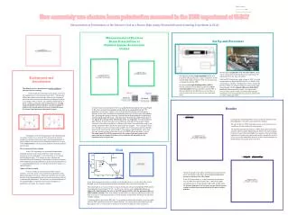
RF scheme of electron linear accelerator with energy 200-500 MeV Levichev A.E. Budker Institute of Nuclear Physics SB RAS
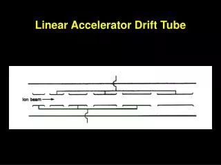
Accelerating structure Accelerating structure. 1 – Regular cell, 2 – Wave type transformer, 3 – Connection cell, 4 – Connection diaphragm, 5 – Structure frame with cooling system.
Accelerating structure BINP produced accelerating structure. Accelerating cells and wave type transformers.
RF power source Basic parameters of TH 2128 C/D klystron. Picture of TH 2100 klystrons series.
Modulator Parameters of К2 modulator series (ScandiNova Systems) Modulator К2-3
Power compression system BINP made SLED type power compression system Main parameters of BINP made power compression system.
Measured input and reflected power from SLED system cavities
Sub harmonic bunching system Sub-harmonic bunching cavity is used to bunch beam before bunching cavity with main frequency. In our case the frequency of sub-harmonic cavity can be chosen as main frequency divided by 8 (357 MHz) or by 16 (178 MHz). To decrease cavity sizes it can be performed by toroidal form. The loss power of cavity is 2-5 kW. The amplifier tube can be used as power source for the cavity. Such power source supplies sub-harmonic cavity with frequency of 178 MHz in preinjector complex VEPP-5 in BINP SB RAS.
RF buncher Electric field in RF buncher along beam axis with storage energy of 1 J RF buncher design Electrodynamics cavity parameters Cavity dimensions
RF scheme for all accelerating structures except the first and second structures
Attenuator and phase shifter I – double T-bend, II – waveguide with two plungers 1` and 2` • Wave amplitude depends on the length between plungers and doesn’t depend on common distance • The phases depend on common distance and don’t depend on the length between plungers
RF scheme of debuncher-monochromatic Basic parameters of the klystron TH 2163 A Parameters of modulators (K1 series) Modulator of К1 series (“ScandiNova Systems”)